Difference between revisions of "Mousetrap Vehicle Competition"
(1003 --> 1004) |
|||
| (43 intermediate revisions by 5 users not shown) | |||
| Line 1: | Line 1: | ||
= Objectives = | |||
Using knowledge of gear ratios, torque, and basic physics concepts, design and build a vehicle that is powered by a standard mousetrap that will travel the farthest linear distance in a competition against other designs. | |||
= Overview = | |||
Vehicles move by propulsion, which is a form of energy conversion from a stored form into movement. The most common means of propulsion is to release the chemical energy in petroleum products to cause movement. The internal combustion engine in most automobiles works this way. Small radio-controlled cars use propulsion when the chemical energy stored in batteries is converted into electricity, and this electricity drives an electric motor that moves the car. | |||
A recent development in automobiles is hybrid propulsion that combines an internal combustion engine and a battery to power a car. With a hybrid car, the battery is used when not much power is needed, and the internal combustion engine is only used when more power is required for acceleration or to recharge the battery. | |||
In many machines, including cars, gears assist by transferring mechanical energy from one gear to another. A gearing system, which uses multiple gears, has a measurable characteristic called a gear ratio. A gear ratio is calculated by counting the number of teeth on the input gear, or the initial gear in the system, and dividing that number by the number of teeth on the output gear, or the final gear in the system. When a system uses wheels or pulleys, the diameter of the gears is used. | |||
and the | |||
Almost any energy source can be used for propulsion with enough ingenuity. For example, a wind-up toy car converts the energy from muscles by winding up the spring and that energy is converted into motion when the car is released. | |||
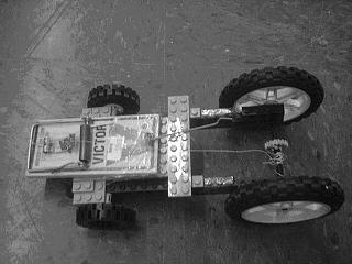
A mousetrap car (Figure 1) is a vehicle that uses a mousetrap as its propulsion source. In a mousetrap car, a string is attached to the lever arm of the mousetrap and the other end of the string is attached to the drive axle. | |||
[[Image:lab_Mousetrap_1.jpg|frame|center|Figure 1: Picture of a typical mousetrap car.]] | |||
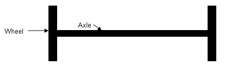
The string is looped around a hook on the axle. As the string is wrapped around the axle (Figure 2), the mousetrap's lever arm is pulled back. When the mousetrap is activated, the lever arm pulls the string, which rotates the drive axle and propels the vehicle forward. | |||
[[Image:lab_Mousetrap_2.jpg|frame|center|Figure 2: A possible mousetrap car design.]] | |||
== Forces Involved in a Mousetrap Car == | |||
'''Friction''': This is the force that resists the motion of two surfaces in contact. In a mousetrap car, power can be lost due to friction between the axles and chassis and between the wheels and the ground. Not all friction is bad; friction that prevents the wheels from slipping is called traction. In general, a design should reduce friction, but have enough traction so that the wheels do not slip. | |||
In a mousetrap car, | |||
and chassis and between the wheels and the ground. Not all friction is bad | |||
general, | |||
traction so that the wheels do not slip. | |||
'''Rotational Inertia''': This is the resistance an object has to changes in rotation. The mass of the object affects the rotational inertia, the greater the mass, the greater the rotational inertia. | |||
mass, the greater the rotational inertia. | |||
[[Image:lab_Mousetrap_3.png|frame|center|Figure 3: Lesser rotational inertia.]] | |||
[[Image:lab_Mousetrap_4.png|frame|center|Figure 4: Greater rotational inertia.]] | |||
Rotational inertia (Figures 3 & 4) is also dependent on the location of the mass from the axis of rotation (Figure 5). The farther the bulk of mass is radially from the axis of rotation, the greater the rotational inertia. | |||
[[Image:lab_Mousetrap_5.png|frame|center|Figure 5: Comparison of rotational inertia.]] | |||
= Competition Rules = | |||
* Only the Lego parts provided may be used | |||
the | * The vehicle must be powered solely by the mousetrap provided | ||
* The vehicle must have at least one wheel (no projectiles allowed) | |||
* The mousetrap spring must not be physically altered | |||
* The vehicle may not receive a push at the start | |||
* The vehicle cannot be touched once it has left the starting position | |||
* Displacement distance will be measured; not the total distance traveled | |||
* If the car hits another object (e.g. the wall), distance will be measured at the point of impact | |||
== Scoring == | |||
The design with the greatest displacement distance traveled wins. | |||
= Design Considerations = | |||
* Consider the power source; the position and length of the lever arm determine the torque produced | |||
* Too much weight may prevent the mousetrap car from moving; weight will also affect the car's momentum | |||
* Use CAUTION when handling mousetraps (mousetrap hammers snap at 70mph) | |||
= Materials = | |||
* A Robolab kit | |||
* A mousetrap | |||
* Kevlar string | |||
* Tape | |||
= Procedure = | |||
and | # Brainstorm possible designs for a mousetrap car. | ||
the | # Sketch the design on paper and have it approved by a TA. | ||
# Construct the design based on the sketch. | |||
# The mousetrap may be attached to the car with tape (try not to use excessive amounts of tape; all tape should be removed from the Lego parts before leaving). | |||
# Load the mousetrap by winding the string around the drive axle. | |||
# Once the design is ready, position the vehicle behind the starting line and release it. | |||
# Once the vehicle comes to a stop, the distance may be kept or quick modifications may be made and additional trials attempted. Each design is allowed up to three trials if time permits. | |||
# Before leaving the room, the mousetrap car must be disassembled and all tape must be removed from the Lego parts. | |||
= Assignment = | |||
== Individual Lab Report == | |||
Follow the lab report guidelines in the page called [[Specifications for Writing Your Lab Reports]] in the ''Technical Communication'' section of this manual. The following discussion points should be addressed in the appropriate section of the lab report: | |||
* Discuss the advantages and disadvantages of the design | |||
* Discuss the characteristics of the design that won the competition | |||
* Discuss the impact of engineering concepts on design and the results | |||
* Include spreadsheet with every team's results. Describe the results and talk about other designs in the class and how you could improve your design | |||
Extra credit will be awarded to the winner of the competition as described in the [[EG1004 Grading Policy]]. Make sure to get the sketch of the design signed by the TA. Get at least one photo of the design and include it to the lab report. | |||
{{Lab notes}} | |||
< | <!-- | ||
== PowerPoint Presentation (EGED I Only) == | |||
Follow the presentation guidelines laid out in the page called [[EG1004 Lab Presentation Format]] in the ''Introduction to Technical Presentations'' section of this manual. | |||
The following discussion points are to be addressed in the appropriate section of the presentation: | |||
--> | |||
{{Laboratory Experiments}} | |||
Latest revision as of 02:28, 31 August 2022
Objectives
Using knowledge of gear ratios, torque, and basic physics concepts, design and build a vehicle that is powered by a standard mousetrap that will travel the farthest linear distance in a competition against other designs.
Overview
Vehicles move by propulsion, which is a form of energy conversion from a stored form into movement. The most common means of propulsion is to release the chemical energy in petroleum products to cause movement. The internal combustion engine in most automobiles works this way. Small radio-controlled cars use propulsion when the chemical energy stored in batteries is converted into electricity, and this electricity drives an electric motor that moves the car.
A recent development in automobiles is hybrid propulsion that combines an internal combustion engine and a battery to power a car. With a hybrid car, the battery is used when not much power is needed, and the internal combustion engine is only used when more power is required for acceleration or to recharge the battery.
In many machines, including cars, gears assist by transferring mechanical energy from one gear to another. A gearing system, which uses multiple gears, has a measurable characteristic called a gear ratio. A gear ratio is calculated by counting the number of teeth on the input gear, or the initial gear in the system, and dividing that number by the number of teeth on the output gear, or the final gear in the system. When a system uses wheels or pulleys, the diameter of the gears is used.
Almost any energy source can be used for propulsion with enough ingenuity. For example, a wind-up toy car converts the energy from muscles by winding up the spring and that energy is converted into motion when the car is released.
A mousetrap car (Figure 1) is a vehicle that uses a mousetrap as its propulsion source. In a mousetrap car, a string is attached to the lever arm of the mousetrap and the other end of the string is attached to the drive axle.
The string is looped around a hook on the axle. As the string is wrapped around the axle (Figure 2), the mousetrap's lever arm is pulled back. When the mousetrap is activated, the lever arm pulls the string, which rotates the drive axle and propels the vehicle forward.
Forces Involved in a Mousetrap Car
Friction: This is the force that resists the motion of two surfaces in contact. In a mousetrap car, power can be lost due to friction between the axles and chassis and between the wheels and the ground. Not all friction is bad; friction that prevents the wheels from slipping is called traction. In general, a design should reduce friction, but have enough traction so that the wheels do not slip.
Rotational Inertia: This is the resistance an object has to changes in rotation. The mass of the object affects the rotational inertia, the greater the mass, the greater the rotational inertia.
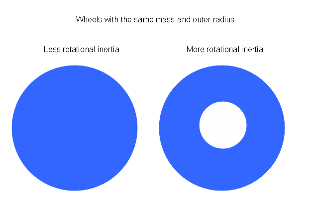
Rotational inertia (Figures 3 & 4) is also dependent on the location of the mass from the axis of rotation (Figure 5). The farther the bulk of mass is radially from the axis of rotation, the greater the rotational inertia.
Competition Rules
- Only the Lego parts provided may be used
- The vehicle must be powered solely by the mousetrap provided
- The vehicle must have at least one wheel (no projectiles allowed)
- The mousetrap spring must not be physically altered
- The vehicle may not receive a push at the start
- The vehicle cannot be touched once it has left the starting position
- Displacement distance will be measured; not the total distance traveled
- If the car hits another object (e.g. the wall), distance will be measured at the point of impact
Scoring
The design with the greatest displacement distance traveled wins.
Design Considerations
- Consider the power source; the position and length of the lever arm determine the torque produced
- Too much weight may prevent the mousetrap car from moving; weight will also affect the car's momentum
- Use CAUTION when handling mousetraps (mousetrap hammers snap at 70mph)
Materials
- A Robolab kit
- A mousetrap
- Kevlar string
- Tape
Procedure
- Brainstorm possible designs for a mousetrap car.
- Sketch the design on paper and have it approved by a TA.
- Construct the design based on the sketch.
- The mousetrap may be attached to the car with tape (try not to use excessive amounts of tape; all tape should be removed from the Lego parts before leaving).
- Load the mousetrap by winding the string around the drive axle.
- Once the design is ready, position the vehicle behind the starting line and release it.
- Once the vehicle comes to a stop, the distance may be kept or quick modifications may be made and additional trials attempted. Each design is allowed up to three trials if time permits.
- Before leaving the room, the mousetrap car must be disassembled and all tape must be removed from the Lego parts.
Assignment
Individual Lab Report
Follow the lab report guidelines in the page called Specifications for Writing Your Lab Reports in the Technical Communication section of this manual. The following discussion points should be addressed in the appropriate section of the lab report:
- Discuss the advantages and disadvantages of the design
- Discuss the characteristics of the design that won the competition
- Discuss the impact of engineering concepts on design and the results
- Include spreadsheet with every team's results. Describe the results and talk about other designs in the class and how you could improve your design
Extra credit will be awarded to the winner of the competition as described in the EG1004 Grading Policy. Make sure to get the sketch of the design signed by the TA. Get at least one photo of the design and include it to the lab report.
Remember: Lab notes must be taken. Experimental details are easily forgotten unless written down. EG1004 Lab Notes Paper can be downloaded and printed from the EG1004 Website. Use the lab notes to write the Procedure section of the lab report. At the end of each lab, a TA will scan the lab notes and upload them to the Lab Documents section of the EG1004 Website. One point of extra credit is awarded if the lab notes are attached at the end of the lab report. Keeping careful notes is an essential component of all scientific practice.
| ||||||||


