Prototyping with Micro-controllers, Sensors, and Materials
Objectives
The first objective of this lab is to utilize the basics of electronics, the Arduino board, and the Arduino IDE (Integrated Development Environment). The Arduino IDE will be used to program the Arduino board. These skills will be used for several hands-on tasks including programming the Arduino to control an LED with a button, taking temperature readings, and designing a basic prototype for a product.
The prototyping will focus on designing and building a thermal insulation device that utilizes a variety of materials; this design will be tested and the resulting data analyzed. Students will be able to see how Arduino can be applied. All designs will be tested with a heated object. The team with the lowest Minimal Design Ratio (MDR) will be declared the winner.
Overview
Electricity
To put simply, electricity is the movement of electrons. Electrons flow through a conductive wire when there is a difference in charge between two points in the wire. This flow of electrons is called electrical current and it is measured in Amperes (A). Due to convection, electrical current flows opposite of the electrons. The difference in charge is called electrical voltage and it is measured in Volts (V). Finally, there are certain materials that resist the flow of electrons. This property is called electrical resistance and it is measured in Ohms (Ω). Resistors are electronic devices that are specifically designed to resist the flow of electrical current. Ohm’s Law is the relationship is detailed below, where V is the voltage across a resistor, I is the current flowing through a resistor and R is the resistance of the resistor.
Electronic Components
There are several basic electronic components used to build simple circuits. Some of these components are polarized which means the way they are connected matters.
DC (Direct Current) Voltage Sources
DC Voltage Sources are used to power circuits because they have a voltage difference across their terminals. DC Power Sources are usually batteries (AA, AAA, etc). Arduino boards can be powered by a battery, a USB cable, or an AC adapter. When the Arduino is powered, it can be used as a 5V DC voltage source. They ARE polarized.
Resistors
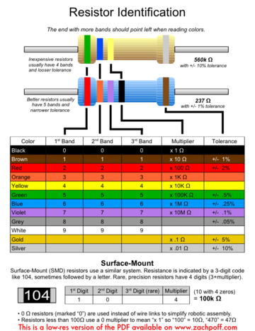
Resistors are components that reduce the amount of current flowing through a circuit and convert the excess current to thermal energy. Resistors can be used to control the voltages and currents of circuits. Resistors are color coded with what resistance they are. They are NOT polarized.
Capacitors
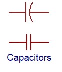
Capacitors are components that can store energy in an electrical field and then dissipate it at a later time. Capacitance is a measure of how much charge a capacitor can store and it is measured in Farads (F). Capacitors resist voltage changes by supplying or drawing current. They are SOMETIMES polarized.
Inductors
Inductors are components that can store energy in a magnetic field and then dissipate it at a later time. Inductance is a measure of how much energy an inductor can store and it is measured in Henrys (H). Inductors resist current changes by dropping or increasing the voltage. They are NOT polarized.
Push-buttons and Switches
Push-buttons and switches are mechanical devices that interrupt or divert current running through them. Basic push-buttons and are polarized while basic switches are not.
Diodes and Transistors (BJT/MOSFETS)
Diodes are components that allow current to only pass in one direction. MOSFETs are electric components that act as electrically controlled switches. They can also be used to amplify signals. They ARE polarized.
Light Emitting Diodes
LEDs are small electric lights that use low voltages and currents. The orientation of the LED is important since it acts like a diode and only allows current to flow in one direction. Most LEDS also require a resistor (typically 470 Ω) in series with them because they will burn out almost instantly when they encounter high current. They ARE polarized.
Microcontrollers
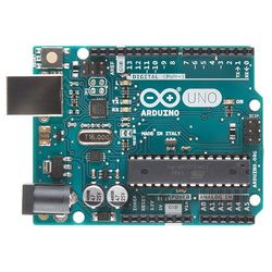
A microcontroller is a cheap, programmable computer without any of the peripherals such as a mouse, keyboard, or screen. Microcontroller boards have direct access to the input and output pins of its processing chip so that the user can directly read from sensors and perform actions. Microcontrollers are present in many electrical appliances like microwaves. Arduino boards were designed to be easily programmed and assembled into larger projects. These boards come in many shapes and sizes and some contain additional features such as WiFi or Bluetooth connectivity. Different boards can also have different features such as processing speed and memory size.
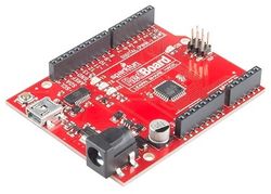
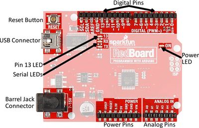
This lab will be using an Arduino UNO board created by SparkFun called a RedBoard.
Arduino Hardware
Reset Button: Restarts the Board
USB Connector: Provides power and connects it to the computer
Pin 13 LED: Usable LED without making an LED circuit
Serial LEDS: Shows if the Arduino is transmitting or receiving data from pins 0, 1 or the USB connection
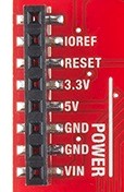
3.3V: Usually used to power low-voltage sensors
5V: Most common power pin used to power circuits
GND: Ground pin which is 0V
VIN: Voltage-In can be used to power the board using a battery
A0-A5: Identical analog pins that can be used to read sensors or control analog devices. Pins A0-A3 are more stable than A4-A5.
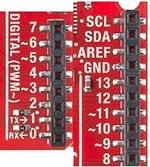
Pins 0-1: Transmit and Receive pins, don’t use these pins for this lab
Pins 2-12: Digital pins that can be switched between HIGH states and LOW states
Pin 13: Connected to the on-board LED, use it only as an input pin
The Arduino IDE
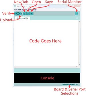
The Arduino IDE is a program that can be used to edit, compile, and upload code to a supported microcontroller. Figure 6 is a screenshot of the program:
Verify: checks code for errors and points to where the errors occurred after it finishes. Upload: verifies code and then uploads it to the Arduino board if there are no errors.
Console: shows any errors the software found in hardware.
Serial Monitor: a tool used to see how a program is running. It’s like a multimeter for the program.
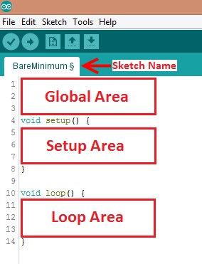
Programs written in Arduino are called sketches. A basic sketch can be broken up into 3 different areas: global, setup and loop; these areas are pictured below.
Global: constants and imported libraries go here.
Setup: activate the pins and sensors used. This code only runs once.
Loop: the code that runs continuously such as reading sensors and turning pins HIGH or LOW.
Arduino Programming
The Arduino programming language is based on C/C++, but it is designed to be simpler and easier to learn. The most intuitive way to think about programming is like building with LEGO blocks: certain rules must be followed and different building blocks can be used to build bigger parts. General
- Every line must either end with a semicolon ‘;’ unless it’s a conditional, loop, or function
- Comments start with a //
- Comments are text that the program ignores
- Used to label and explain code
Datatypes Datatypes are the different kinds of data values that can be used, manipulated and stored using C++. The table below includes the most basic and widely used datatypes.
| Datatype | What it stores (examples) | Default value | Notes |
|---|---|---|---|
| Boolean | A true value (1, TRUE, HIGH) or a false value (0, FALSE, LOW) |
0, FALSE, LOW | - |
| int | An integer number (-5, 15, 1047, etc.) | 0 | Can be positive or negative |
| double | A decimal number (-0.5, 123.77, etc.) | 0 | Can be positive or negative |
| char | A single character (‘c’, ‘A’, ‘5’, ‘?’, etc.) | Indeterminate | Must be enclosed in single quotes |
| string | A sequence of characters (“Hello World!”, “10”, “157+5”, etc.) |
Empty (“”) | Must be enclosed in double quotes |
Operators Operators perform operations on variables and constants. The results of these operations are usually stored in a variable. The table below includes common operators.
| Operator | What it does | Notes |
|---|---|---|
| = | Assigns a value to a variable | |
| + | Adds two or more values | |
| - | Subtracts two or more values | |
| * | Multiplies two or more values | |
| / | Divides two or more values | |
| ++ | Increment by 1 | Usually used in loops |
| -- | Decrement by 1 | Usually used in loops |
| == | Checks if two value are equal | Usually used in conditionals |
| != | Checks if two value are not equal | Usually used in conditionals |
| > or < | Less than/Greater than comparison | Usually used in conditionals |
| <= or >= | Less than/greater than or equal to comparison | Usually used in conditionals |
| && or || | Boolean AND or Boolean OR Used to cascade multiple Boolean operations | Usually used in conditionals |
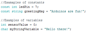
Constants and Variables Constants and variables hold data according to their datatype. They need to be given a name so they can be referred to later. Constants hold data that will NOT change while a program is running. Constants usually contain pin numbers or sensor threshold values. Variables contain data that WILL change while a program is running. Variables usually contain sensor values and other values that need to have mathematical operations done on them. Below is an example of how to create different constants and variables.
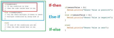
Conditional Statements Conditional statements run code enclosed by their curly brackets when a condition is met.
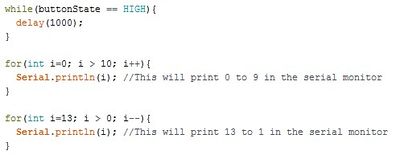
Loops Loops run the code enclosed by their curly brackets a specific amount of times or until a condition is met. While-loop While-loops are used to perform a task until a condition is met For-loop For-loops are used when you want something to run a specific number of times. Although they seem complicated at first, the structure of most for-loops is the same. In the parenthesis, the first part sets a variable (usually ‘i’ for ‘index’) to a value used to begin a count, the middle is the condition when the loop stops, and the third part is where you increment or decrement the counting variable.
Commonly Used Arduino Functions
| Function | What it does |
|---|---|
| pinMode(pin,mode) | Sets a pin as an input or output |
| digitalWrite(pin, value) | Sets a digital output pin to HIGH or LOW |
| digitalRead(pin) | Reads an digital input pin as HIGH or LOW |
| analogWrite(pin, value) | Sets an analog output pin to a value 0-1023 |
| analogRead(pin) | Reads an analog output pin as a value 0-1023 |
| delay(milliseconds) | Pauses the program for a certain amount of time |
| Serial.print(value) | Prints the value (variable) to the Serial Monitor. |
Thermal Insulation
Heat is a form of energy. Heat transfer is thermal energy that is transferred from one body to another as a result of a temperature difference. Temperature is the measure of the average kinetic energy of atomic motion. The faster the atoms are moving, the higher the temperature.
The specific mechanisms that convey energy from one location to another are conduction, convection, and radiation.
When there is a temperature difference within a solid body or between two solid bodies in contact with each other, energy (heat) will flow from the region of higher temperature to the region of lower temperature. This is known as conduction.
Imagine a metal rod that is heated at one end. The atoms of the rod collide at the point where the temperature differs, transferring heat until the temperature of the rod becomes uniform.
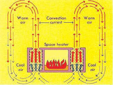
Convection is the transfer of heat within a fluid medium (fluids consist of gasses and liquids). Convection can occur in two different ways. Convection occurs as natural and forced convection. Forced convection occurs when the main mechanism for heat transfer is due to the forced flow or motion of the fluid.
Today we heat our homes through radiators using natural convection. Air flows through a heating element and then is dispersed through the room.
Suppose you wanted to disperse the heat even faster. In that case you could blow a fan past the heating elements. This is forced convection; it is one of the principles used in air conditioners to have a relatively small unit cool a large space.
According to the Encyclopedia Britannica, radiation is the process by which energy, in the form of electromagnetic radiation, is emitted by a heated surface in all directions. It does not require an intervening medium to carry it. The heating of the Earth by the Sun is an example of heat transfer by radiation.
Electromagnetic radiation is a mean of energy transfer that occurs when an atom absorbs energy. This EM wave can propagate as heat, light, ultraviolet, or other electromagnetic waves depending on the type of atom and the amount of energy absorbed.
Color is a property of light; when an object appears white, it virtually reflect all the EM waves coming to it while a "black" object absorbs it all. Therefore, color (reflectivity) is to be considered when choosing materials for thermal insulation.
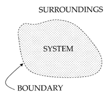
Your container is a thermodynamic system – a part of the Universe separated from the surroundings by an imaginary boundary. There are three types of systems: open systems, closed systems and isolated systems.
Open systems are systems where transfer of mass and heat is possible. For example, an open pot of boiling water is an open system – it exchanges heat with the air around it and water vapor. If collected, the water vapor can be condensed back to liquid water which has some mass.
Closed systems are systems where only heat can be transferred to the surroundings. A hermetically sealed bottle of soda is a closed system. If placed in a hot environment it absorbs energy in form of heat but the amount of liquid within does not change.
Isolated systems are systems which do not interact with the surroundings at all. No exchange is possible - neither heat nor mass. An ideal Thermos® is an isolated system. If hot chocolate is poured within, you will get the same amount back at the same temperature. No such system can be fabricated but can be approximated.
Now that we understand how heat is transferred, we must consider how to slow it down. Understanding how to minimize heat loss is the key to designing a successful insulating container.
The first consideration is the materials you choose. Using materials that are poor conductors of heat, like glass, will minimize heat loss.
Plastic is also a poor conductor of heat. Foam cups are made of plastic which have tiny air bubbles suspended in it. Air is among the poorest conductors of heat. A vacuum, or the complete lack of air, is the best insulator of all. This is the principle employed in the Thermos design.
The other important consideration in creating your container is its cost. Minimal design uses the fewest resources while maintaining the safety and efficacy of your product.
Thermocouples consist of two wires of dissimilar metals and are usually welded together or attached on a junction. When the temperature at a junction changes, it generates thermoelectric potential (emf) which is proportional to the temperature difference between the two junctions. This voltage difference can be used to measure the temperature at that junction.
Materials and Equipment
- Arduino UNO microcontroller and USB cable
- Computer with Arduino IDE
- Breadboard and jumper wire
- Resistors
- 220 Ω
- 2.2 kΩ
- 10 kΩ
- Thermistor
- LED
- Pushbutton
Procedure
Starting a new sketch in Arduino
- Open the Arduino IDE
- Plug the Arduino/RedBoard into the computer
- In the Arduino IDE toolbar, go to Tools > Board and select “Arduino/Genuino Uno”
- From the Tools toolbar, select the correct port
Building Circuits on a Breadboard
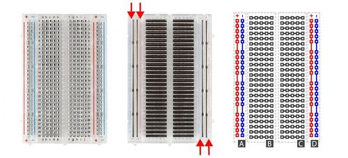
Breadboards are small boards that are commonly used for circuit prototyping. They allow the connection of components that were discussed previously without making permanent connections.
Activity 1: Building an LED Circuit
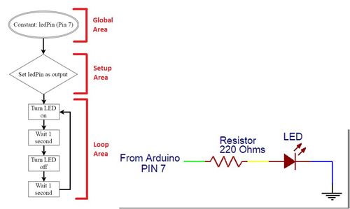
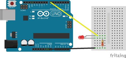
- The first activity will be making a simple LED blinking circuit. The programming flowchart and circuit diagram are in Figure 14.
- First, wire the LED to the breadboard like in Figure 15. Remember, since LEDs are polarized, their orientation matters. The shorter leg of the LED should be connected to the same row as GND. The resistor is NECESSARY, otherwise too much current would flow and the LED will burn out! Make sure to wire power to the power (red) rail and the signal from 7 to the LED directly
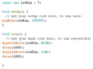
- Now type the following code into a new sketch.
- The flowchart uses Digital Pin 7 on the Arduino as an output. Therefore, create a constant that holds the number 7 and in the setup area set Pin 7 as an output using pinMode. Then, turn the LED on by using digitalWrite, have a delay of one second, turn the LED off by using digitalWrite and then set another delay of one second.
- The LED circuit will be used in the next activity. Do not deconstruct it.
Activity 2: Using a Button
- Activity 2 adds a button to the circuit from activity 1 and requires conditionals (think if-statement). The LED should be on when the button is pressed and off when the button isn’t pressed.
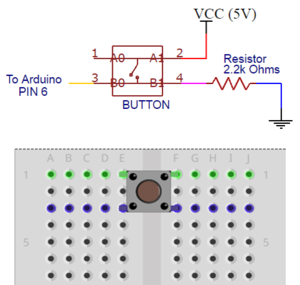
- Before you breadboard the circuit look at the bottom side (pin side) of the button to examine which pins are connected.
There is a line connecting the pins that are wired together internally on each side. See the schematic below, pins 1 and 2 are connected, and pins 3 and 4 are connected. Make sure the button straddles the break in the breadboard
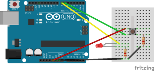
- First, breadboard the circuit diagram in Figure 18 and sketch a flowchart of the program needed. Have a TA verify the flowchart.
- Write the Arduino program to implement the flowchart. Use an if statement
- Remember to create a constant that holds the pin number to which the button is connected and that the button will be a digital input. After the button constant, create an integer that will hold the button state:
- Within the loop function, you must check the state of the button (whether it is pressed or not pressed), using the following code:
Activity 3: Prototyping a Thermal Insulation Device and Product Evaluation
Competition Rules
The following rules must be observed at all times during the competition. Violation of any of these rules will result in the disqualification.
- You must use a cup or clay in the design of your thermal insulation device
- In order to protect the wax from being ruined, no materials may be poured on top of the jar
- Students are not allowed change the placement of the thermistor with respect to the lid
- The container may not be held
- External heat sources are prohibited
- The candle must be inside the container within 30 seconds from when you receive it
Materials with Price List
- Large foam cup - $0.50
- Lid - $0.25
- Pack of clay - $0.20/bag
- Wool fabric pieces - $0.10/2 pieces
- Cotton balls - $0.05/3 pieces
- Popsicle sticks - $0.01/stick
- Paper cup - $0.40
- Styrofoam pieces - $0.05/3 pieces
- Tape - $0.10/ft
- Aluminum foil - $0.30/ft2
- Plastic wrap - $0.02/ft2
"NO RETURN" POLICY: When calculating cost, you must include
ALL materials you request, even if you end up not using them. Make your selections carefully so you don't end up with cost that hurts your performance, but has no benefit.
Competition Procedure
Building a Thermistor
-
Using the Arduino, the temperature change of the candle will be recorded over the course of 15 minutes. The Arduino will read the temperature through the thermistor and print out the values into serial monitor.
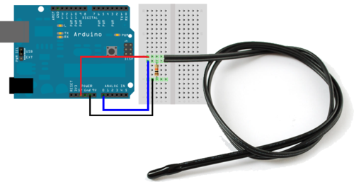
- Carefully remove the existing circuit, and wire the circuit according to the following configuration. A 10 KΩ (Brown, Black, Orange) resistor should be used. Make sure that pin A0 is used, and the circuit is powered to 5V and grounded.
- Download the program here: https://drive.google.com/open?id=1XTx0EHq4knP3qQIawumjvxLWdxH4rp1T There are missing components in the code; make sure to read through the comments and insert code where it is necessary. After the program is completed and uploaded, open up the Serial Monitor to check if the readings are correct (should be in the 70s °F range). Keep the circuit intact since it will be used to measure the temperature of your container.
- Notes: A thermistor is a thermal resistor, which is a resistor that changes resistance with temperature. Depending on the temperature that it detects, the amount of voltage that goes through the thermistor will change proportionally to the temperature. Using the output voltage of the thermistor, it can be converted to a temperature reading. The Arduino should be taking a temperature reading every 5 seconds. The analog voltage value read through pin A0 should then be converted to a Fahrenheit reading. The temperature reading should be printed to the Serial monitor along with the seconds timestamp of the reading.
Insulating Container Design
- Analyze your materials and consider your design options, keeping in mind the lab's specifications. Make sure you make preliminary sketches during this process.
- Now, sketch your design. Label your drawings clearly. Prepare a price-list for your insulating container based on the materials you have chosen.
- Build your insulating container based on the sketch you just completed. Your TA will provide the materials needed for your design. If you decide to modify your design during the construction of your insulating container, note the changes and describe the reasons for them. If the modifications required more materials to be used, make sure you update your price list and your TA approves it.
Competition
- Have a TA test your Arduino code. Run the program for approximately 30 seconds to obtain an average room temperature. The data from the Arduino can be seen in the Serial Monitor on the top right corner of the Arduino IDE.
- Stop the program after 30 seconds and check to ensure that the data was collected.
- The TA will bring the candle to you once you are ready to receive it. Place the lid with the thermistor attached over the top of the wax. Be sure the top of the container is loosely covered with the lid.
- Do not adjust the thermistor from its position in the lid.
- Do not screw on the lid; just place it over the container. Warning: Be careful! The hot melted wax is HOT!
- Restart your Arduino program. Once the temperature readings stop increasing, start timing your 15 minute run.
- The data from the thermistor will allow for further analysis. The Arduino data from the Serial Monitor will be used to attain the IC for the competition calculation. PLEASE DO NOT CLOSE OUT OF THE SERIAL MONITOR WINDOW. After 15 minutes (or 900 seconds), copy the data from the serial monitor into an Excel file.
Data Analysis
- The data pasted from the Serial Monitor into Excel is not correctly separated into columns; therefore, to put them in the correct format, highlight all the data, and go to Data -> Text to Columns -> Delimited, and check off comma. Press finish to see the data in the correct columns.
- Create a graph using the X, Y Scatter template. You'll find the template on the Insert tab, under the Charts group, with the Scatter icon. Click on the arrow below the icon and select the top left icon in the pulldown gallery. You can get the axes you want by clicking on the axis. You can get labels and titles by clicking on the chart, which will change the ribbon to the Design tab. In the Charts Layout group, click the icon that looks like the chart you want. Right click on the things you want to change.
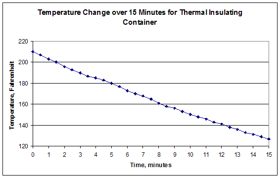
- For the thermistor name the X-axis Time, name the Y-axis Temperature. Plot it in half minute intervals for fifteen minutes, starting from the downhill trend. You may need to divide the Arduino data by 60 to convert to minutes. You may select the intervals based on your results. When you are finished, your graph should look similar to Figure 22.
- Calculate the Insulating Capacity (IC) of your design, do not include the first few seconds of an uphill trend, this is just the thermistor changing from room temperature to the temperature of the wax. IC The IC is the value of the slope of the graph of fifteen minutes of data. The IC is calculated using the data from the Arduino for this lab.
- Add a trendline to your graph. To do so, click on the chart to get the Design tab on the ribbon. Under the Chart Layouts group, click on the chart template that has a trend line. As before, right click on the various items to make them what you want, including deleting things. Finally, right click on the trend line. This will bring up the Format Trendline window. On the left side, the Trendline Options item should be highlighted. If it isn't, click on it to highlight it. On the right side near the bottom is an item Display Equation on chart. Click on the check box to the left of this item and click Close. You can then click on the equation that's on the chart to move it where you want.
- Calculate the Minimal Design Ratio (MDR) for your design: IC is the insulating capacity you calculated earlier. Cost is the cost of your container, TR is the temperature of the room given to you by the TA, and TF is the final temperature read by the thermistor. Check the MDR using data from all the devices for a better reference. Again, please use IC from Arduino to calculate the final MDR.
Note: If your average room temperature is significantly different from the TA's average, let the TA know.
The team with the lowest MDR wins.
Your lab work is now complete. Please clean up your workstation. Return all unused materials to your TA.
Assignment
Individual Lab Report
Follow the lab report guidelines laid out in the page called Specifications for Writing Your Lab Reports in the Technical Communication section of this manual. As you write, the following discussion points should be addressed in the appropriate section of your lab report:
- Describe the basics of Arduino and its application
- Explain heat, heat transfer and all the mechanisms that perform heat transfer. Discuss which of these mechanisms applied to your design
- Define what thermal insulation is and the different types of thermodynamic systems
- Discuss minimal design and its importance
- Describe your container's design. Explain the choices you made. Make sure you include a discussion of the materials you chose and why. Talk about your team's strategy for winning the competition
- What changes would have increased/decreased your MDR or IC?
- How did your team derive the IC value?
- Should the Temperature vs. Time graph be smooth or should it have spikes? Explain how closely your curve approximates the ideal and what would affect the readings you recorded
- Describe how your design succeeded or failed. Discuss design improvements
- Include spreadsheet with every team's results. Describe the results and talk about other designs in the class
Note: It is not unusual to experience instrumentation errors in this lab, leading to incorrect temperatures being recorded. Be sure to read How to Handle Unusual Data in the online manual to learn how to handle this.
Remember: Lab notes must be taken. Experimental details are easily forgotten unless written down. EG1004 Lab Notes Paper can be downloaded and printed from the EG1004 Website. Use the lab notes to write the Procedure section of the lab report. At the end of each lab, a TA will scan the lab notes and upload them to the Lab Documents section of the EG1004 Website. One point of extra credit is awarded if the lab notes are attached at the end of the lab report. Keeping careful notes is an essential component of all scientific practice.
Team PowerPoint Presentation
Follow the presentation guidelines laid out in the page called EG1004 Lab Presentation Format in the Introduction to Technical Presentations section of this manual. When you are preparing your presentation, consider the following points:
- What is the importance of prototyping and using Arduino?
- What is the importance of minimal design?
- What is the importance of materials in prototyping?
- Why is it important in today's world to minimize heat loss?
- What is the importance of proper data collection method and automation?
- Is there any benefit to using one data collection method over the other?
- How would you improve your design?





 IC is the insulating capacity you calculated earlier. Cost is the cost of your container, TR is the temperature of the room given to you by the TA, and TF is the final temperature read by the
thermistor. Check the MDR using data from all the devices for a better reference. Again, please use IC from Arduino to calculate the final MDR.