Sensors (EV3)
This writeup is intended for use with the EV3. For the NXT version, see Sensors.
Objectives
The experimental objective of this lab is to design various Mindstorms programs that use rotation, light, touch, and ultrasonic sensors.
These exercises will build a foundation of experience with sensors programming that can be used with the semester-long design project.
Overview
Mindstorms Program
Before we can learn to use sensors, we must become familiar with the EV3. Remember that the Mindstorms program is a compiler: a program used to make other programs. Just as a compiler is used when creating and debugging a C++ program, Mindstorms similarly compiles programs for the EV3. The Mindstorms interface is graphic; a text compiler like those used for C++ is not. However, the principle is very much the same. Actions are taken based upon circumstances set by the programmer.
The EV3 houses all the programming instructions that control the movement of your robot. Once you have created your program in Mindstorms, it is uploaded to the EV3. The EV3 then dictates the robot's motion. If your robot does not do what you intended, you must rewrite the program in Mindstorms and upload the corrected version to the EV3.
Materials and Equipment
- Lab PC
- Mindstorms Software
- USB Cable
- EV3 Unit
Procedure
Rotation Sensor
For this portion of the lab, you will learn how to use the rotation sensor in the motor to determine the distanced your robot moved.
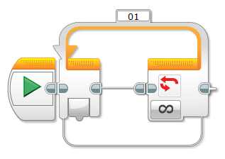
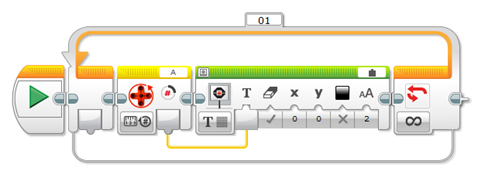
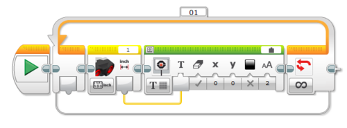
- Click on the orange tab and select the Loop block. Connect it to the Start block.
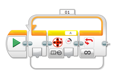
- Click on the yellow tab and select the motor rotation block. Insert it into the loop block.
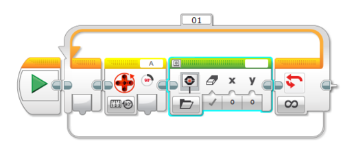
- Click on the green tab and select the display block. Insert it into the loop block.
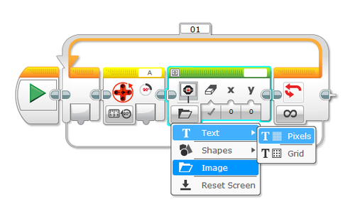
- Click on the image button on the display block. Change it to Pixels.
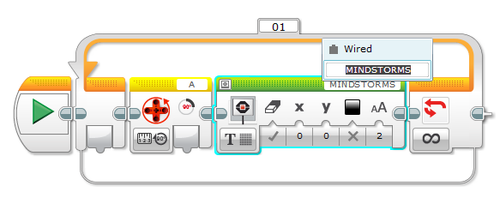
- On the top right corner of the display block, click on MINDSTORMS and change it to Wired.
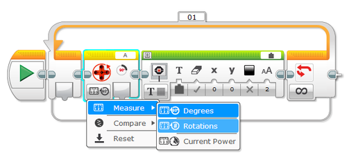
- Click on the measurement button on the motor rotation block and change the measurement to rotations.
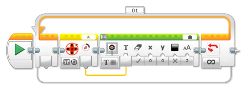
- Wire the Motor Rotation block to the Display block by clicking and dragging the mouse from the tab on the motor rotation block to connect to the text input on the display block.
With the program now completed, upload it to your EV3 and run the program. Turn the motor that is connected to port A and look at the display. You should see numbers on the display that correspond to the number of times you've turned the motor.
Example for Rotation Sensor
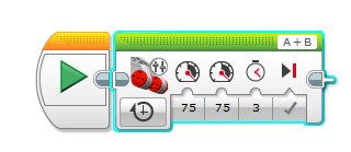
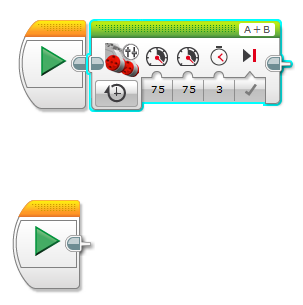
Suppose you wrote a program that had your robot's motors move forward for 3 seconds.
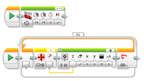
Let's say you want to add the code that we previously made so that you can read the number of rotations that your robot made while it's moving. In order to do that, you'll need to create a new sequence beam.
- Start by clicking on orange tab and selecting the start block. Insert it anywhere on the screen.
- Create the program previously made on the start block
Example #2 for Rotation Sensor
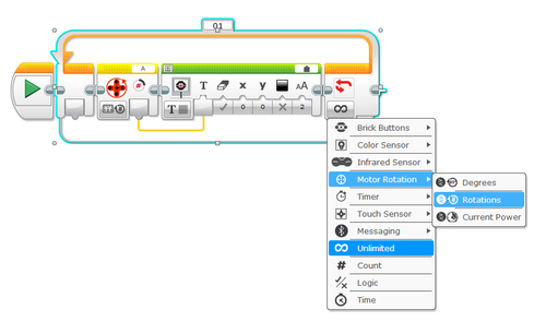
Suppose we wanted to create a program that displayed the number of rotations, but instead of having it loop forever, it would stop measuring the number of rotations once you've rotated it three times.
- Create the program shown below
- Click on the infinite button in the loop block and change it to rotations.
- Set the threshold value to 3 and make sure that the comparison type is greater than.
When you run this program, you should be able to see the number of rotations on the EV3's display. If you make more than 3 rotations on the motor, the program should end.
Ultrasonic Sensor
For this portion of the lab, you will learn how to use the ultrasonic sensor in order to determine the distance between the robot and an object.
The code for obtaining a distance reading and displaying it on the EV3's screen is almost exactly the same as the code for the rotation sensor. The only difference is that instead of the rotation sensor block, you must use the ultrasonic sensor block
Example for Ultrasonic Sensor
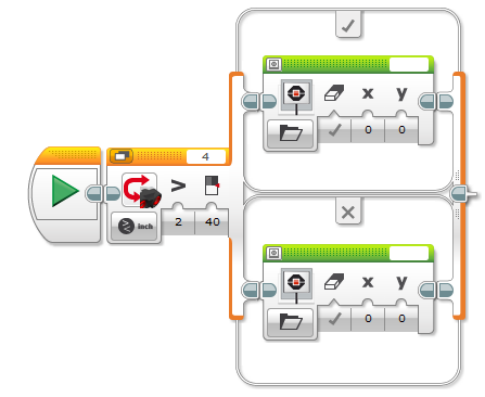
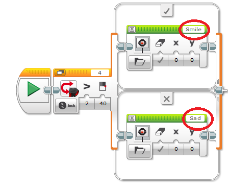
Suppose we wanted to write a program in which our EV3 would show a happy face if the Ultrasonic Sensor detected a distance greater than 40 in, and show a sad face if the Ultrasonic Sensor detected a distance less than 40 in.
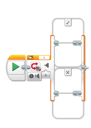
- To start off this program, we'll first need the switch block, which can found by clicking on the orange tab
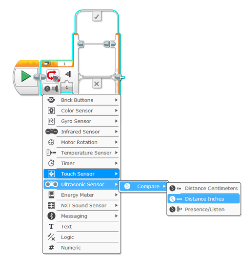
- On the switch block, click on the button and configure it to compare the distance in inches
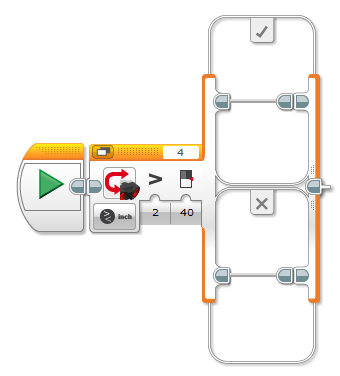
- In the configuration panel, change the compare type to greater than, and set the threshold value to 40 in.
- Place a display block into each of the two cases beams in the switch block
- Configure each display block so that it shows the correct image. Remember that the EV3 should display happy face when the distance sensed by the Ultrasonic Sensor is greater than 40 in and show a sad face when the distance is less than 40 in.
- Place the entire switch block into a loop block.
Example #2 for Ultrasonic Sensor
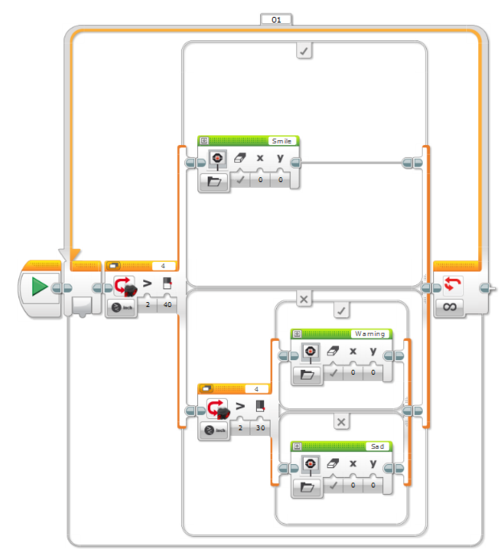
Now suppose we wanted to add an additional case to the program where the EV3 would display a caution sign when the Ultrasonic Sensor senses a distance less than 40 in but greater than 30 in, and display a sad face when the distance sensed is less than 30. In this situation, one switch case won't be enough, as the program will only check to see if the value obtained is greater than or less than one specific number. To overcome this problem, we'll need an additional switch case inside of the switch case we already have.
In this program, when the distanced sensed is greater than 40, it will display a happy face, just like before. When the distance sensed is less than 40, it will check to see if it's greater than or less than 30, and show the appropriate image based on that.
Task
Create a program in which your robot maintains a distance of 8 and 20 in from the wall. In other words, your robot should move away from the wall if the ultrasonic sensor senses a distance less than 8 in and moves towards the wall if the ultrasonic sensor senses a distance greater than 20 in.
Touch Sensor
For this portion of the lab, you will learn how to use the touch sensor to control the actions of your robot based whether the touch sensor has been pressed or bumped.
Example for Touch Sensor
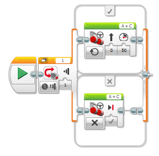
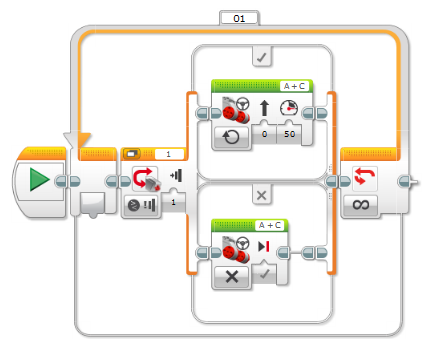
Suppose you wanted to create a program in which your robot would move when the touch sensor is pressed, and would stop when the touch sensor was released.
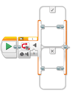
- Insert a switch block and have it set to the touch sensor
- Insert a move block into each of the sequence beams. Configure one motor block to move continuously and set the other motor block to stop
- Place the switch block into a loop block
Light Sensor
For this portion of the lab, you will learn how to use the light sensor in order to determine the light intensity of the sensor's reflected light. You will also learn how to use the light sensor to follow a line.
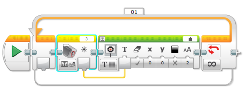
The program for obtaining the light intensity and displaying it on the EV3's screen is the same as that of the rotation sensor and the ultrasonic sensor, except you need to use the light sensor block.
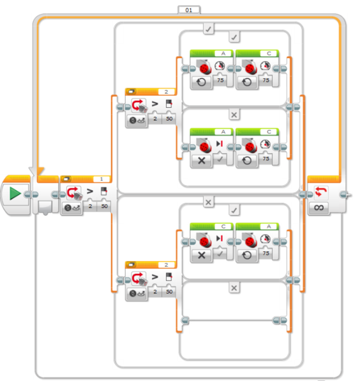
Line Following Code Using One Light Sensor
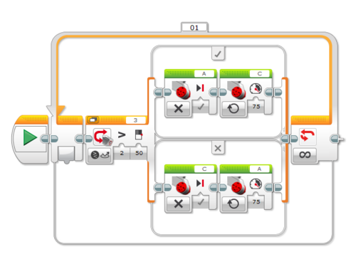
The code for following a line using one light sensor is shown below.
This block of code alternates between the left and right motor of the robot, depending on whether the light sensor sees the line. For example, let us assume that motor A is the left motor and motor C is the right motor. Thus, when the light sensor sees the line, the right motor (motor C) stops while the left motor (motor A) starts turning. This causes the robot to turn away from the line while moving forward. Also, when the light sensor doesn't see the line, the left motor stops while the right motor starts turning. This causes the robot to turn towards the line while moving forwards.
Line Following Code Using Two Light Sensors
The code for following a line using two light sensors is shown below.
This block of code alternates between turning the left and right motor of the robot, depending on which light sensor sees the line. First, let us assume that motor A is the left motor and motor C is the right motor. Also, we'll assume that light sensor 1 is the left light sensor and light sensor 2 is the right light sensor. Thus, when the left light sensor sees the line, but the right line sensor doesn't, the left motor stops while the right motor starts moving. If the right light sensor sees the line, but the left light sensor doesn't see the line, the right motor stops while the left motor starts moving. If neither light sensor see the line, then both motors start turning.
For positioning, the robot should be placed such that the light sensors are in between the line.
Tasks
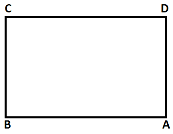
Course 1
Create a program in which your robot travels from point A to point C in a clockwise manner, then rotates 180 degrees and finally returns to point A.
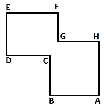
Course 2
Create a program in which your robot travels from point A to point H in a clockwise manner, rotates 180 degrees, and travels to point C.
Assignment
A zip file including the following programs needs to be submitted to the EG Website. If you don't know how to make a zip file, read the page How to Compress Your Files in the Instructional Presentations section of this manual.
Lab Report
There is no lab report for this lab.
Team PowerPoint Presentation
There is no presentation for this lab.
| ||||||||
