Difference between revisions of "Sandbox/Lemon"
(Created page with "= Objectives = The experimental objective of this lab is to study the principles of a reduction oxidation reaction, and to learn about how a capacitor stores energy. In order to…") |
Ldemetrious (talk | contribs) |
||
| Line 1: | Line 1: | ||
=== Energy Conversion: Introduction to Lemon Powered Vehicle Competition === | |||
= Objectives = | = Objectives = | ||
The experimental objective of this lab is to study the principles of a reduction oxidation reaction, and to learn about how a capacitor stores energy. | The experimental objective of this lab is to study the principles of a reduction oxidation reaction, and to learn about how a capacitor stores energy. | ||
Revision as of 13:35, 18 July 2017
Energy Conversion: Introduction to Lemon Powered Vehicle Competition
Objectives
The experimental objective of this lab is to study the principles of a reduction oxidation reaction, and to learn about how a capacitor stores energy.
In order to learn how battery cells, capacitors and different reducing agents work, we will construct a lemon citrus cell and use the cell to power two different devices.
You will design and build a car that is powered either by a lemon battery or a capacitor (charged by a lemon battery). Your car will be entered in a competition against the other students' cars in your section.
Overview
Chemistry behind a Citrus Cell
A battery is a device that is usually made up of one or more individual cells. In this experiment we will be creating a citrus cell. A battery cell is a cell that creates a voltage across a terminal of 2 dissimilar metals. This is done through a chemical half reaction. A citrus cell is one that does this using a citrus juice as the electrolytic solution. By using 2 different types of metals we have 2 different reaction potentials which directly affect the voltage produced with each cell. By linking multiple cells together in series we produce a battery.
Before learning the concept behind a battery cell, there are two properties that should be understood: electronegativity and ionization energy:
- Electronegativity in an element is a measure of the element's capability to attract another element's electrons. The higher degree of electronegativity an element has the more power it has to pull away electrons from a less electronegative element. There is an obvious trend in the periodic table for this particular property. Electronegativity generally increases from left to right and from bottom to top. As a result the elements around cesium have very low electronegativity and elements around fluorine have the highest.
- Ionization energy is the amount of energy required to remove an electron from an atom to form a cation. A cation is an ion or group of ions having a positive charge in electrolysis. This property also has a trend in the periodic table. It generally increases from left to right and from bottom to top.

The electronegativity and ionization energy values for the metals used in the lab are provided in the table below:
| Metal | Electronegativity (Pauling Scale) |
Ionization Energy (kJ/mol) |
|---|---|---|
| Magnesium | 1.31 | 738 |
| Nickel | 1.91 | 736 |
| Copper | 1.90 | 745 |
| Zinc | 1.65 | 904 |
| Aluminum | 1.61 | 577 |
These two properties give the metals their reactive traits.
The reaction that takes place in the lemon cell is called a redox reaction. This reaction can be simplified into two parts and they are called oxidation and reduction. Oxidation happens when there is an electron loss and reduction is when there is an electron gain. Oxidation and reduction can be shown in a half-reaction, which clearly shows the electron transfer. Take for example the redox reaction between magnesium and oxygen.

When magnesium reacts with oxygen, magnesium loses electrons making it oxidized:

At the same time, oxygen gains those electrons making oxygen reduced.

These are the half-reactions of the magnesium and oxygen redox reaction. Be aware that the electrons in the half-reactions are not given a state, that is because they are being transferred and don't have a definite state. If these reactions were separate then the electrons would have to travel through a wire or some medium to get to the other side, causing the two half-reactions to have a potential between each other. This potential is the voltage between the two half-reactions.
An electrochemical cell is where two electrodes are in contact with an electrolyte. The electrodes are conductors (usually metallic) used to form a contact with a nonmetallic part of a circuit such as an electrolyte.[1] The electrolyte provides an abundance of ions to the reaction. The electrode at which oxidation occurs is called the anode and is the source of electrons that flow inside the cell. This creates a shortage of electrons at the electrode, so the anode is the positive part of the cell. The electrode at which reduction occurs is called the cathode and is the destination of these electrons. This creates a surplus of electrons at the electrode, so the cathode is the negative part of the cell.
Looking at the cell externally, this means that the cell supplies electrons at the cathode, the electrons flow through whatever the cell is powering, and are collected at the anode. Early scientists understood the concept of the flow of current, but did not know about electrons, so they arbitrarily said that electrical current is defined to flow from the positive (anode) to the negative (cathode) electrodes of a battery. This means that current flow is in the opposite direction of electron flow.

Electrochemical Cell: Daniell's Cell
A type of electrochemical cell is shown above. The path of electron travel is shown clearly by the red line. This electrochemical cell is more specifically called a Daniell's Cell. There is a salt bridge separating the half-reactions. This salt bridge is present to provide each side with ions. Oxidation of Zn in the galvanic cell produces Zn+ ions, also reduction of Cu- ions. Without the salt bridge to connect the half-reactions and bring ions the reactions would not continue. The ions from the half-reaction would plate the other electrode, and the reaction would slowly stop when the ions have finished plating the opposite electrode. The reaction 'poisons' itself.

The concept of a Daniell's Cell when applied to a commercial battery is called the Leclanché cell. In a Leclanché cell there are two electrodes and an electrolyte and they are separated using a porous material. This material only lets the ions pass through, therefore preventing direct interaction of the two half-reactions.[3]
Electrical Components
In electrical engineering different electrical components are represented by different symbols. Below a few of them are shown:


A cell is a single unit for the conversion of chemical energy to electrical energy. A battery is comprised of multiple cells linked together.
A capacitor is an electrical device used to store charge temporarily. Some capacitors can be used in place of a battery but they operate very differently from one. A capacitor is charged by a voltage source logarithmically, as shown in Figure 5.

Because of their design, these capacitors are sensitive to the polarity of the voltage applied to them. The capacitors used in this lab must be connected with the proper polarity, or they will fail. Therefore, be sure to check the capacitor used to make sure you have the negative sign on the capacitor connected to the negative applied voltage. Failure to do this will cause the capacitors to fail.

The total energy a capacitor holds is given by the equation E = CV2 ⁄ 2. Note that the energy that the capacitor holds is proportional to the square of the voltage.
A diode is a device that allows current to pass through it in only one direction. This means that it has polarity, and will only allow current to pass from its positive side to its negative side. a Light Emitting Diode (LED) not only passes current, but also lights up when it's passing current.
Different combinations of electrical components allow engineers to design different devices. Resistors, inductors, and capacitors can be arranged in three different ways. In a series circuit, the element's conductors are connected end to end. The current in a series circuit remains the same in all the electrical elements. In a series circuit, as shown in Figure 7, the sum of the voltages across each element is equal to the voltage of the power source (Vout = VA + VB + VC).

In a parallel circuit, as shown in Figure 8, the element's conductors are connected at opposing ends. The current that is supplied by the voltage source equals the current that flows though elements D and E. The voltage across the elements that are parallel is the same (Vout = VD = VE).

The motor provided is a 9V motor that will operate with voltages lower than 9V with reduced torque and speed. A motor with no load draws 9 milliamps; a stalled motor draws well over 350 milliamps. By increasing the voltage provided to the motor you can increase the motor speed. By increasing current you increase the torque.
Design Considerations
- Which electrode pair yields the most voltage per unit cost?
- Which circuit configuration will provide a more desirable voltage across the load? Parallel or series?
- Which aspects of the competition formula are most advantageous?
Materials and Equipment
- Lemons
- Lemon Juice
- Magnesium
- Nickel
- Zinc
- Copper
- Aluminum
- 3 Alligator cable sets
- 1 Farad 2.5V Capacitor
- Standard Lego Car Chassis plus Lego parts kit
- Lego to Alligator Cable Clip Connector
- LED (Light Emitting Diode)
- Small cups
- Scissors
- Tape
- DMM (Digital Multi-meter)
- Paper/styrofoam Plates
Materials with Price List (Part 3)
- Capacitor: $1.00
- 2oz Lemon Juice (with cup): $0.25
- 1.5" Mg Strips: $1.00
- Cu Strip: $0.25
- Zn Strip: $0.50
- Al Strip: $0.25
- Ni Strip: $0.25
- Lemon Car Components: $0.00
Warning: Magnesium is a highly reactive metal. Use carefully and only as described in these instructions.
Procedure
NOTE: This lab makes use of liquids. Please do as much work as possible on the tray/plate provided and wipe up spills immediately.
Part 1: Determine Voltage output of different metal electrode pairs
- Obtain two different samples of metals from your TA (two each). TA's will select different metal combinations for each team.
- Take the lemon and squeeze/roll it so that the lemon juice inside the pulp is released, without puncturing the lemon.
- Before inserting one of the metal strips into the lemon, be sure to clean the metal strips. Using emery paper provided by your TA, scrub the emery paper on the metal strip in one direction several times. Then, scrub the metal strip in the direction perpendicular to the direction before. Now that they are clean, insert one metal into the lemon.
- Half a centimeter away insert the other metal piece parallel to the first, so that they are close but do not touch.
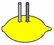 Figure 9: Lemon Cell
- Connect one end of the first alligator cable set to one of the metal pieces and one end of the second alligator cable set to the other metal. These will be the electrodes of the cell.
- Connect the other ends of the alligator cable sets to the positive and negative ends of the digital multi-meter and measure the voltage. Record the value in units of volts. (Note: If it is negative then the polarity is switched, switch the alligator clips to connect to the opposite sides of the DMM)
- The metal strip attached to the positive end of the digital multi-meter (red wire) is the anode (+) and the other (black wire) is the cathode (-).
- Record the values and present them to your TA. The TA will generate a spreadsheet with the voltage produced by each metal combination for all teams.
- Remove the electrodes to stop the chemical reaction. Wipe them clean with a paper towel. Discard the paper towel in the trash can.
- Warning': magnesium left in the lemon juice dissolves.
Part 2: Light up LED and verify polarity
- First, you need to test if your LED works.
- Repeat steps 2-4 in Part 1 to create a second citrus cell.
- Insert the metals into the first lemon to reactivate the first citrus cell.
- Connect the first lemon's anode to the second lemon's cathode using the alligator cable set. Now you have created a lemon battery.
- Measure the voltage in the lemon battery using the digital multi-meter and record it. Following the formula for linking batteries in series, the voltage should be doubled. If it is lower try taking the electrodes out and plunging them into a different part of the lemon.
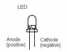 Figure 10: Light Emitting Diode (LED)- note polarization
- Now connect the LED to the lemon battery in the right polarity. Place a hand over the LED and observe it to see if you see any light. If it does not light connect a third lemon cell in series. Does it light up? Why or why not?
- Clean and return all electrodes.
Part 3: Lemon Powered Car Design
- Your car must be designed/built to enter the lab competition. The power must come from either an on-board lemon battery (4 cells maximum) or an on-board capacitor (previously charged from a lemon battery). The car designed for the lemon battery will obviously be larger and heavier than one designed for the capacitor.
- Assess your materials and consider the data established from Part 1. Choose materials for your lemon car design, keeping in mind the Competition Ratio. Make sure you make preliminary sketches during this process.
- For your convenience lemon juice and small cups will be provided for this portion of the lab. You may cut the cups to reduce weight and somehow fasten the electrodes. The lemon juice will provide a better electrolytic solution than a lemon. Lemons have membranes that limit chemical reactions.
- Since your lemon car can be powered by either a lemon battery or a (lemon battery charged) capacitor you may modify it any way you deem fit. Sketch your design in pencil using the graph paper provided on the EG website http://eg.poly.edu. Label your drawings clearly. Prepare a price-list for your lemon powered car based on the materials you have chosen. Use the results your class determined from Part 1 of the experiment. Have your TA sign the sketches and the price-list.
- Your TA will provide the materials needed for your design. If you decide to modify your design during the construction of your car, note the changes and describe the reasons for them. If the modifications required more materials to be used, make sure you update your price list and your TA approves it.
- Before entering the competition, test if your motor is working.


Competition
Since your lemon car can be powered by a lemon battery, a (lemon battery charged) capacitor, or a combination of both, the start procedures for the competition are different.
For the lemon battery, start the chemical process by pouring lemon juice into the cups. For the capacitor, make sure that it has been charged for at least 15 minutes according to the instructions in Part 3, and be careful to not short out the capacitor --- it will take another 15 minutes to recharge.
When requested by the TA, the student will position the lemon powered car and either allow the car to run (lemon battery design) or connect the alligator clips to the capacitor (capacitor design).
The competition will be won by the team that has the highest competition ratio:
![{\displaystyle CR={\frac {distance\left[{\text{ft}}\right]}{1\left[{\text{s}}\right]+time\left[{\text{s}}\right]}}\times {\frac {100}{Cost\left[\$\right]}}+distance\left[{\text{ft}}\right]\,}](https://wikimedia.org/api/rest_v1/media/math/render/png/a0643569de9df32ae019a6925b9b94366fc82c0e)
The TA will record the test data after 60 seconds or when the car stops moving, whichever occurs first. The linear distance from the starting point will be measured. The TA will then calculate the competition ratio. The tabulation for the whole class will be provided.
Your lab work is now complete. Please clean up your workstation. Return all unused materials to your TA. Refer to the Assignment section for the instructions you need to prepare your lab report.
Assignment
Team Lab Report
Note: Since this lab is a competition, you will be writing a team lab report rather than an individual one. See the Team Authoring Strategies page in the Technical Communication of this online manual for guidance of how to do this.
Follow the lab report guidelines laid out in the page called Specifications for Writing Your Lab Reports in the Technical Communication section of this manual. As you write, the following discussion points should be addressed in the appropriate section of your lab report:
- Describe the electrochemical cell in your introduction. What consequences did the electrode voltages have for your design decisions? Use appropriate part 1 experimental values.
- What factors did you consider in designing your Lemon-Powered Car? Did you use any of the background information?
- Include what background information was used to aid in your design
- What was the competition ratio for your design?
- What important design characteristics should a winning Lemon-Powered Car include to achieve the highest possible design ratio?
- Describe how your power source design succeeded or failed.
- Discuss design improvements. How would you optimize the design (i.e., improve the ratio) based on experience?
- Describe the concept behind the lemon battery.
- Describe the power source chosen for the design.
Team PowerPoint Presentation
Follow the presentation guidelines laid out in the EG1003 Lab Presentation Format section of this manual. When you are preparing your presentation, consider the following points:
- Since one term in the competition ratio is cost, present the cost of your vehicle. Use the page How to Show Cost Data in Presentations for instructions on how to do this.
- How would you improve your lemon-powered car?
Footnotes
- ^ Wikipedia. 16 Aug. 2005 http://en.wikipedia.org/wiki/Electrode
- ^ a b Based on McGraw Hill Drawing
- ^ Atkins, P.W., Beran, J.A.. General Chemistry(second edition). American Books, 1989
| ||||||||