Introduction to 3D Printing Inventor
Objective
In this exercise, drafting software used by technical professionals will be introduced. Basic technical design methods will be shown using computer-aided design (CAD) software, specifically AutoDesk Inventor. Later on, this knowledge can be incorporated in your semester-long design project by constructing physical prototypes with 3D printing.
To practice this prototyping procedure, a NYU Logo keychain will be created in Autodesk Inventor and exported to be 3D printed. The members of the winning team of Lab 1C: Mousetrap Vehicle Competition will each receive a 3D-printed keychain.
Overview
Computer-Aided Design
CAD programs (Inventor, AutoCAD, Revit, SolidWorks, SketchUp) allow engineers to make precisely scaled drawings. These drawings can be used to manufacture equipment and construct infrastructure and allow designers to display their designs with complete specifications and detail. Orthographic views (top, bottom, side, front, back, etc.) can be used to document every aspect of the technical drawing needed for production while isometric views can be used to view the final 3D representation of the product.
This exercise will teach the basics of Autodesk Inventor, 3D file formats, and the basics of 3D printing. After this lab, you will be able to create simple 3D files and set them up to be 3D printed.
3D Printing
3D printing allows for rapid prototyping and onsite manufacturing of products. Plastic 3D printing has led the way for new techniques with new materials such as aluminum, bronze and even glass. Biomaterials are also being incorporated such as 3D printing ear cartilage and liver tissue. As the 3D printing industry grows, 3D printing will become a big part of many engineering fields.
In this course, 3D printing can be used to produce SLDP course modifications, robot parts and a team logo for extra credit.
Procedure
Setting up the file
- Start AutoDesk Inventor and open a new file.
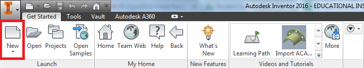 Figure 1: Inventor Toolbar
- Select the measurement system you would like to use (for this lab English) and select a Standard (in).ipt file.
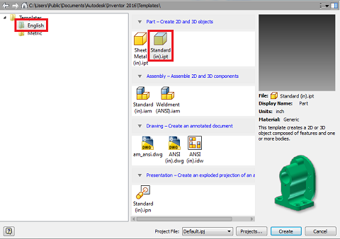 Figure 2: Inventor new file options


Designing the NYU Keychain

- The first step to designing the keychain is to draw the base shape as follows:
- “Start 2D Sketch”
- Select Select the XZ plane
- Rotate the camera to orient the top correctly
- Select the rectangle tool
- Draw a 2.6” x 0.7” rectangle starting at the origin
- These values can be typed in (switching what value is changed is done using the tab key)
- Select the circle tool
-
- Draw a 0.7” diameter circle centered in the middle of one of the short sides of the rectangle (the cursor should snap to the center position and turn green when you get close)
- Draw another circle 0.45” in diameter in the same position
-
- Fillet (round) sharp edges
- Select the fillet tool from the “Create” section of the toolbar
- Select one of the the two intersecting lines that form the right angles on the base
- Use the default fillet size of 0.125” and repeat on the other corner
- Your sketch should look like Figure 3
- Remove the extra lines using the trim tool
- Select the trim tool from the “Modify” section of the toolbar
- Select all interior lines that divide the keychain (as shown in the picture below)
- If you are receiving errors remove the dimensions on the rest of the keychain
- Your Sketch should look like Figure 4
- Exit the sketch using the finish sketch button
- After creating a 2D sketch the next step is to use that to create a 3D object. In this lab we will be using the extrude tool to create a 3D block; however, in the future you may want to use revolve or other tools too create more advanced geometry.
-
- Select the “Extrude” tool from the “Create” section of the toolbar
- Select the profile of the object you would like to extrude (in this case the shape we just drew)
- Change the extrusion thickness to 0.15” and press Enter.
- Your model will look like Figure 5
- Select the “Extrude” tool from the “Create” section of the toolbar
-
- The next step is to add our design to the key chain. For this lab we are going to use a vector graphics file in the dxf format provided by NYU; however, in the future you could design your own logo directly using the sketch tool.
- Download the NYU Tandon Vector Logo (This logo was converted from the file provided on NYU's identity page)
- Select “Start 2D Sketch”
- Select the top surface of the key chain
- Rotate the camera again to orient the top correctly
- Select the “ACAD” option from the “Insert” toolbar
-
- Select “Files of Type” .dxf and open the downloaded design (this may take a moment)
- Select “Next” on the “Layers and Objects Import Options” window
- Check the “Constrain End Points” and “Apply Geometric Constraints” boxes
- Select “Finish”
- Settings are shown in Figure 6
- If the computer freezes use the alt+tab hotkey to check if DWG trueviewer is reporting an error
-
- For this side of the key chain the “Tandon School of Engineering” portion of the logo is not needed.
- Select the bar and everything to the right using click and drag
- Delete this portion with the “Delete” key on the keyboard (Not Backspace)
- Next the logo needs to be scaled to fit the key chain. To keep the spacing of the design we need to select an appropriate base point. In this case we will use the midpoint of the line on the right side of the box.
- Use the line tool to trace over the line on the right side of the box
- Select the point tool under the create section of the toolbar
- Place a point at the center point of the line that was just drawn
- Select the “Scale” tool from the “Modify” section of the toolbar
- Select the box and torch of the logo by clicking and dragging
- Select the midpoint that was just placed as the base point for scaling
- Enter a scaling factor of 0.75
- Next the logo needs to be positioned on the keychain
- Select the entire logo and use the “Move” tool from the Modify section of the toolbar to move it off the base so there is space to draw the alignment line
- Select the line tool and draw a 0.7” line from the middle of the right side of the circle towards the center of the keychain
- Select the logo using the move tool again, this time making sure to use the midpoint created earlier as the basepoint.
- Place the basepoint at the end of the alignment line
- Exit the Sketch
- The final sketch is shown in Figure 7
- To finish this side of the keychain the design needs to be cut into the base. To do this the extrude tool will be used again.
-
- To cut the design select “cut” in the shape menu.
- Select the profile of the design to cut, in this case the area around the torch and each of the letters
- Select a depth of 0.06”
- The final model is shown in figure 8
-
- To 3D print the design you will need to export the file as an STL. This is the only format that can be opened by the 3d printing software.
- Click the Inventor Logo in the top left
- Select “export” then “CAD format”
- Select .stl from the dropdown menu and name the file
- Before pressing save select options and reselect inches as the unit.
- This ensures that the keychain remains its scale when imported into the printing software.
- The last step of the keychain is to make the white insert that will fit in the center to make it 2 colors.
- Click “My Home” in the bottom file tabs
- Start a new file
- Create a rectangle with dimensions 2.2”x0.65”
- Extrude the rectangle 0.12”
- This model is shown in Figure 9
- Export this in the same way as before
- Make sure to reselect units again


Preparing to print


- Now that the logo is designed the next step is to put it together in the 3d printing slicer software. This software is used for orienting the parts on the printer and selecting the color of each object. It also generates the toolpaths that the printer will follow to print the objects. The software used in EG is MakerBot Desktop.
- Open the software and select “add file” open the stl containing the base of the key chain
- Using the rotation tool orient the part so that the torch is facing up
- Press lay flat in the translation tab to move the keychain down onto the bed
- This step is very important to make sure the print starts smoothly on the bed
- Select add file again, this time open the filler rectangle
- Orient the part correctly using the rotation tool
- To vertically align the part open the translation tool and type in 0.15mm as the Z value
- Horizontal alignment can be done by eye
- Select one piece and change the extruder under the info button
- If the info button does not appear change the device type to Replicator Dual (under Devices > Device type)
- Save the file as a .thing (under file > save)
Assignment
A *.thing file must be submitted to eg.poly.edu. It is required for a lab report grade.
| ||||||||