Computer Aided Design Competition
Please review the CAD Guide presentation that explains the fundamentals of CAD software prior to performing this lab. The presentation is listed underneath the title Lab 2 on the EG1004 Lab Manual.
Objective
The objective of this lab is to use Autodesk Fusion 360 to modify a three-dimensional structure to increase its minimum safety factor while minimizing any increase in volume. The structures will be evaluated in competition using a design ratio dependent on the change in the structure’s safety factors and volumes.
Overview
Computer-Aided Design
Computer Aided Design (CAD) uses computer software to create, modify, or analyze models of three-dimensional products. CAD software allows engineers to efficiently create dimensioned, scaled drawings to manufacture equipment and build infrastructure. CAD software can display orthographic views (top, bottom, side, front, back) that can be used to document the technical specifications in drawings needed for production while axonometric views (isometric, dimetric, trimetric) show the final 3D representation of a product. Autodesk 360, AutoCAD, Revit, Dassault Systèmes SolidWorks, and Sketchup Free are examples of CAD software.
This exercise will introduce fundamentals of CAD using Autodesk Fusion 360.
Fusion 360
Autodesk Fusion 360 is a cloud-based software that uses remote servers hosted via the Internet to process, store, and compute data. This CAD software creates precisely scaled drawings. These drawings are turned into 3D models that are used to visualize designs through photorealistic renderings and to simulate how a design performs under applied forces or loads.
The two workspaces in Fusion 360 that will be used in this experiment are Design and Simulation (Figure 1). The Design workspace creates mechanical designs that contain information about geometric constraints, and the Simulation workspace simulates applied loads on a design to observe the design's performance under those loads.

There are two tabs -- Create and Modify -- in the Design workspace. The Create and Modify tabs contain the functions needed for sketching and building a 3D model. They create and modify sketches when in Sketch mode (Figure 2).

A Sketch creates the 2D shapes that are the bases for all 3D models. When first sketching the shapes, they do not have to have accurate dimensions or scale. Using the Sketch Dimension tool and the Constraints functions, the base shape and 3D model can be edited without starting over (Figure 3).

Once a sketch is complete, the Create and Modify tabs are also used to generate the 3D model (Figure 4).

The Extrude, Sweep, and Loft tools are used to give direction and depth to the 3D model. Extrude projects the initial sketch outward to create a model. The Sweep tool creates a 3D model of a predetermined surface (profile) along a specific path. The Loft tool creates a 3D extrusion to connect two profiles of any shape (Figure 5). The Sweep and Loft tools are particularly useful for creating extrusions at an angle.

The Loft/Sweep Tutorial video demonstrates how to use these tools. Table 1 shows common Fusion 360 shortcuts.
| Command | Windows Key Combination | Mac Key Combination |
|---|---|---|
The Timeline function located at the bottom of the screen contains a record of the design history that can be modified or manipulated. The controls located to the left can be used to visit previous actions (Figure 6). The middle button will play the design history as an animation. The gray slider on the timeline can be dragged to different areas to show the design at a given stage. Actions can also be removed from the timeline and the design will automatically update itself if errors do not occur later in the timeline.
The Simulation workspace can run simulations to test how a design will perform under real-world conditions. A Static Stress simulation, for example, analyzes the deformation, stress, and safety factor of a design from structural loads and constraints. The assumptions used in the simulationare based on a linear response to stress when the load being applied is known and constant. The results determine if a design will deform excessively or fail (break) from the loads applied. To run the tests, loads and constraints are placed on the design.
Constraints consist of fixed, pinned, and frictionless support options that prevent motion in specific directions. Fixed constraints prevent all motion and displacement of a part (Figure 7). This would mimic a screw holding a part in place. A pinned support prevents movement in radial, axial, and/or tangential directions, but allows a part to rotate. Frictionless constraints prevent movement normal to the surface. This mimics a wall or floor to prevent motion perpendicular to the surface.

A load is the force being applied to the design (Figure 8). The force is characterized by the direction, the point of application, and the magnitude of the force being applied.

A Mesh is a boundary along the design made up of polygons that determine the precision of the analysis test (Figure 9). At every vertex, the analysis is run, and results are provided. The more polygons that are generated in the mesh, the more precise the results will be, but the longer it will take to run the simulation and produce the results. Always generate a new mesh when a part is altered.

Safety factor is the ratio of how much stronger a material is than the expected load. It is the measure of the load a material can sustain before permanent deformation or fracture. A common, acceptable safety factor is at least 3, and any value below that is unacceptable and will likely lead to structural failure.
The physical properties of certain materials dictate how they behave under applied loads. The Young’s modulus, or modulus of elasticity, of a material is the measure of the stiffness of that material. It is described as the tendency of a material to deform axially when a force is applied in the axial direction. The yield strength of a material is the point at which the material begins to deform plastically, and the shape of the material is permanently altered. The ultimate tensile strength (UTS) of a material is the maximum stress that the material can withstand before structurally failing, which usually involves bending permanently or breaking (Table 2).
Table 2: Allowed Materials and their Properties Material Aluminum Steel Copper Lead Modulus of Elasticity (GPa) 69 200 118 14 Yield Strength (MPa) 275 207 33 9 Ultimate Tensile Strength (MPa) 310 345 210 18
Materials and Equipment
- A lab PC
- Fusion 360
Procedure
Part 1. Setting up the File
- Launch AutoDesk Fusion 360, click Create Account, and fill in the information. Important: Make sure to use an NYU email (Figure 10).

2. Learning Exercise
This section will e a simultaneous activity. The TA will be making the part at the same time as the students.
- Download Screwed Bracket
- Change the workspace from Simulation to Design in the top-leftmost drop down. Set the units of the drawing to millimeters. The Units setting is found in the Browser on the left side of the window under Document Settings.
- Select one of the inner faces and start a 2D Sketch by clicking Create Sketch' (Figure 11).
- Create a Center Diameter Circle with a diameter of 14 mm by clicking on the center of the existing circular cut. Press on Finish Sketch (Figure 12).
- Go to Create --> Extrude, which will be used to create a cylinder. Select both contours (Figure 14). Change the Extent Type to To Object. Select the opposite inner face (Figure 15).
- Select one of the base faces and begin another 2D Sketch. Select the 2-Point Rectangle from the Sketch section of the toolbar (Figure 16).
- Draw a 10 mm x 6 mm rectangle starting by clicking once at one of the vertices of the flat border (Figure 17) to place one point of the rectangle and click one more time to place the second point of the rectangle. The lengths can be type in before placing the second point of the rectangle (switching which value is changed is done using the Tab key). Press Finish Sketch.
- Select the perpendicular face nearest to the rectangle (drawn in the previous step) and start a 2D Sketch. Draw a 10 mm x 4 mm rectangle 8 mm from the base. The horizontal side of the rectangle must be parallel to the previous sketch (Figure 18). To assure this is true, select both lines by keeping Shift pressed and go to Constraints --> Collinear as shown in Figure 19. then select Finish Sketch.
- Go to Create --> Loft. Select the previous two rectangle as Profiles. Scroll down and change Operation to New Body (Figure 20).
- Click on Construct --> Midplane and select both of the inner walls (Figure 21).
- Go to Create --> Mirror. Select the Loft as the Object and the Plane as the Mirror Plane (Figure 22). This part should look like Figure 23.
- Select the central base and start a 2D Sketch. Draw two 5 mm Center Diameter Circles with the origin on the center line 8 mm from the edge (Figure 24). Finish the Sketch.
- Start a 2D Sketch on the midplane. Click on Create --> Arc --> 3 Point Arc. Place the first and the second points in the centers of both of the circles created in the previous step, as shown in Figures 25-26. Place the third point that needs to be placed in the middle of the other points. Using Create --> Sketch Dimension select one of the end points and the middle point, drag the dimension to the side, as show in Figure 27 and set it to be 9 mm. Finish the sketch, If the arc endpoints shifted, apply a coincident constraint to the arc endpoint and the center of their respective circles.
- Go to Create --> Sweep. Select the two circles created in the previous step as Profiles and select the Arc as the Path. Go to Operation and choose New Body (Figure 28). It should look like Figure 19. Save the design.
- Create a New Design and make a 2D Sketch by selecting any plane and create a rectangle 5 mm x 26 mm, as seen in Figure 30. Extrude the rectangle by 1 mm (Figure 31).
- A vector graphics file will be used in the DXF format provided by NYU. In the future, a logo can be designed using the Sketch tool. Download the Tandon Logo DXF File (this logo was converted from the file provided on NYU's identity page).
- The downloaded ZIP folder must be extracted. Select Insert DXF under the Insert' section of the toolbar (Figure 32).
- The Insert DXF information dialog will appear on the right side of the window. For the Plane/Sketch, select the top surface (Figure 33).
- Click the folder icon next to the Select DXF file to upload the Tandon Logo DXF File. The logo should appear (figure 34). Move the logo away from the origin by dragging it with your mouse (Figure 35). Alternatively, highlight the entire logo, and use the Modify --> Move/Copy tool to move it.
- If the Tandon Logo imports incorrectly, as shown in Figure 36, follow Steps 21-22. Otherwise, skip to Step 23.
- Select the Modify --> Move/Copy' tool. For Move Object, select sketch objects. For Selection, click and drage to select the entire Tandon logo. For Move Type, select rotate. For Axis, select the top horizontal line and set the angle to 180°, as seen in Figure 37.
- Repeat Step 21, but for Axis, select the right vertical line and set the angle to be 180° (Figure 38).
- The imported Tandon logo is shown in Figure 39.
- The vertical bar and Tandon School of Engineering portions of the logo are not needed. Select the bar and text to the right by clicking and dragging (Figure 40). Delete this portion with the Delete key on the keyboard (not Backspace).
- The logo must be scaled to fit the part. A base point must be selected to scale the sketch. The midpoint of the line on the right side of the box around the torch will be used as the base point, so a point must be placed there first.
- Before placing a point, the sketch must be in editing mode. A sketch is in editing mode when the background turns into guidelines, and Finish Sketch appears at the top right of the window. Edit the logo by selecting Browser --> Sketches and double-clicking on the tandon_logo_white sketch (Figure 41).
- Select the Create --> Point tool. Place a point at the midpoint of the right side of the box around the torch (Figure 42). This is the base point.
- Right click the bottom left corner point of the box around the torch, When selected on the correct point, select Delete Coincident (Figure 43).
- Select the Modify --> Sketch Scale tool. The Sketch Scale information dialog will appear on the right hand side of the window. For the Entities, circle the remaining lines of the box and torch of the logo by clicking and dragging. Do not select the midpoint created in Step 27. if the midpoint was selected, clicking on the point again will unselect it.
- Switch to Point and select the midpoint created in Step 27 (Figure 44).
- In the Sketch Scale window, a third option will appear as Scale Factor. enter a scaling factor of 4.5 and click OK (Figure 45).
- Drag and re-locate the logo so it fits cohesive with the sizing. It should look like the logo in Figure 46.
- Create a 2D sketch on one of the main faces where the logo was inserted. Go to Create --> Text. Make the box smaller than the face, as shown in Figure 47. Type in the designer's name and format it so it is Bold and will be visible and cohesive with the size of the part. Some recommended setups are shown in Figure 47. After writing, finish the sketch. It should look like Figure 48.
- The design must be cut into the base. To do this, the Extrude tool will be used.
- To cut the design, select Create --> Extrude on the toolbar. The Extrude information dialog will appear on the right hand side of the window. Select the design profile, which is the area around the torch and each of the letters.
- In the Extrude window, scroll down to Operation, and select Cut. Then set the Distance to 0.2 mm (Figure 49). Click OK. Save the design and return to the Bracket.
- The final model is shown in Figure 50.
- An assembly between the Plate and Bracket must be made. The Bracket file will be used. In this case, the engraved Plate will be the one floating, which means that it will be the one moving to arrange the pieces in the desired order. In the Bracket file, click on Show Data Panel in the top left corner, as shown in Figure 51.
- Once opened, the preview of the Plate should be visible (Figure 52). Click and drag the Plate from the left to the right, where the main screen with the part is. Drop the Plate here. It should look like Figure 53. Press OK.
- Both parts must be listed as components to create Arrangements between them. The Plate was imported as a component already, now the main part is the only on missing. To do this, right click on Bodies and select Create components from Bodies (Figure 54). This will create four different components.
- Click on Modify --> Move/Copy and switch from Bodies to Components, as seen in Figure 55. Select the midpoint of the Plate (Figure 56). Modify the Plate so it matches the orientation on Figure 57 by licking the round circles and rotating it. Press OK.
- The position of the Plate needs to be exact. Go to Modify --> Align (Figure 58) and click the back of the engraved Plate and the lower wall of the part. The order matters as it will move one part to the other. If the part is oriented incorrectly, click on Flip and then OK. It should look like Figure 59.
- Use the Align feature again and press the left border of the Plate and the inner border of the left wall of the part, as shown in Figure 60. Do the same with the bottom border of both parts, as shown in Figure 61. If the plate is oriented incorrectly, use the Flip option to re-orient the Plate.
- At the end, it should look like Figure 62.
Part 3. Fusion 360 Competition
Competition Rules
- This portion of the lab is a competition that requires the redesign a part. The highest competition ratio wins.
- The redesigned part must have a safety factor of at least 3
- The redesigned part must not have more than double the volume of the original part
- The applied forces and fixed constraints cannot be altered
- The thickness of the base and the proportions of the original part cannot be altered. *The supports can be altered if and only if they do not take away from or add to the *base of the part
- The winning design will receive extra credit towards the lab report grade for this lab
- Only aluminum, steel, copper, or lead may be used when modifying the part
- Equation (1) will be used in the competition. The volume will be measured in cubic millimeters.
![{\displaystyle Competition\ Ratio=[{\frac {Final\ Safety\ Factor}{Final\ Volume}}-\ {\frac {Initial\ Safety\ Factor}{Initial\ Volume}}]\times 10^{4}\,}](https://wikimedia.org/api/rest_v1/media/math/render/png/c830a81dc12b9e6aa7074bc16c512ee051d91571)
(1)
Design Consideration
- Do not simply add a long or large block to the redesigned part
- Consider bridges, cranes, and other systems that use structural support in the redesign
- Consider which material will increase the safety factor
- How can the part be modified to support higher loads?
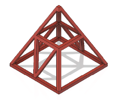
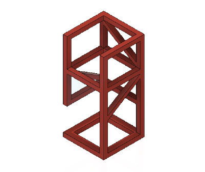
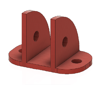
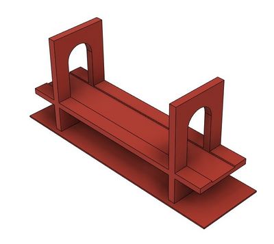
Parts Selection
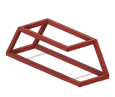
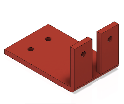
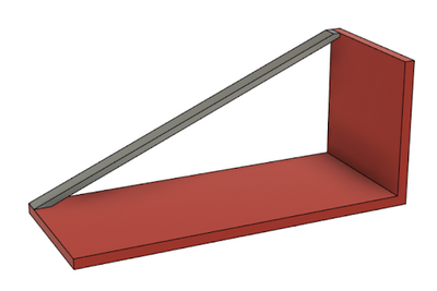
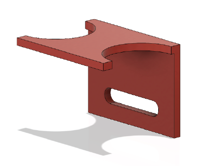
Click on the image of the part to download the Fusion 360 file for that part. Figures 63 through 70 show the components that cannot be modified in red. The red areas cannot be cut, made longer, or thicker. Components, such as fillets, chamfers, or other extrusions, including lofts and sweeps, can be added.
Procedure
- Download the part to be modified as determined by the Lab TA. Extract the ZIP folder that was downloaded to obtain the F3D file.
- Open Fusion 360. Go to File → Open and select the downloaded part. Select the Design workspace in the top left of the window (Figure 71).
- Open the Bodies in the Browser on the lefthand side of the window, right click on the body of interest, and click Properties (Figure 72).
- From the Properties dialog, record the volume of the body in cubic millimeters.
- Click the workspace drop-down menu at the top left of the window and change the workspace to Simulation.
- Open the Static Stress study in the Browser, and open the Study Materials tab (Figure 73). Record the material being used.
- Determine the location the load is being applied (Figure 74). Double click the blue force arrow and record the magnitude of the force in Newtons.
- In the Browser, select Mesh → Generate Mesh (Figure 75). If the mesh is already generated and an error occurs, select OK.
- In the Browser, right click Results and select Solve. Follow the Solve dialog until the simulation is complete. Click Close and the results should look like Figure 76.
- Record the safety factor for the design.
- Sketch a possible solution that would add extra support against the force being applied, remembering what cannot be modified. Recall that the modified design must have a safety factor of at least 3. Have the sketch approved by a TA.
- Go back to the Design workspace in Fusion 360 and use the tools shown to add support to the original part (i.e. Extrude and Sweep).
- Once the part has been modified, go back to the Simulation workspace.
- Change the material of the part, as it can increase the safety factor by right clicking on Study Materials in the Browser tab (Figure 77).
- Click on the Study Materials (Figure 78) to open the drop down menu and change it to one of the four metals (Aluminum, steel, copper, lead.
- Run the analysis again with the modified part by selecting Mesh → Generate Mesh in the Browser.
- Solve the results and record the safety factor of the modified design. The design may become bent as the results are exaggerated in the simulation to gain a better understanding of how the part performs with an applied load.
- If the safety factor of the modified parts is less than 3, add additional supports and/or change the material of the part and run the simulation again.
- Once the required safety factor has been achieved, record the safety factor and volume of the modified part. Give the values of the safety factor and volume of the modified part to the TA to calculate the competition ranking.


Assignment
Individual Lab Report
Follow the lab report guidelines laid out in the EG1004 Writing Style Guide in the Technical Writing section of the manual. Use the outline below to write this report. Please only discuss the Fusion 360 competition portion in the lab report - Do not discuss Parts 1 and 2 in this report.
- Abstract
- Briefly summarize the lab exercise. Include the competition results
- Introduction
- Discuss the uses and advantages and disadvantages of CAD software
- Define safety factor and discuss the physical properties of materials observed in the lab
- Discuss Fusion 360
- Workspaces
- Tools and other components used in the lab exercise
- Discuss the competition
- Present ratio in Equation Editor and discuss ratio
- Discuss rules
- Discuss available materials
- Discuss design strategy and impact of rules, materials, and ratio on design strategy
- Procedure
- Materials
- Describe what was done in sufficient detail so that another person could follow description and replicate results. Reference tools and workspaces used
- Data/Observations
- Present and discuss first Fusion 360 simulation. Include simulation and all data
- Present and discuss all additional simulations. Include simulations and all data
- Present and discuss design ratio. Include the calculation using Equation Editor and initial and final safety factor and initial and final volume
- Present and discuss competition results. Include all data and table
- Conclusion
- Analyze competition results
- Discuss role of safety factor, volume, materials in determining competition results
- Discuss ways to improve the design’s performance in the competition
- Analyze competition results
- Contribution statement
Team PowerPoint Presentation
Follow the presentation guidelines laid out in the EG1004 Lab Presentation Format in the Technical Presentations section of the manual. When preparing the presentation, consider the following points.
- Why is CAD software, such as Fusion 360, AutoCAD, or SolidWorks, an important tool for engineers?
- Include the four basic CAD drawing views (top, most detailed side, front, and isometric) of the mechanical part before and after modifications (eight drawings total)
- How is simulation used in engineering design?
- Explain the material selected for the redesign of the part
- Define safety factor and discuss the physical properties of materials observed in the lab
- How did having a constrained volume impact the design process?
- How did the redesign compare with other redesigns?
- Did the material have an impact on the safety factor, and if so, why?
Appendix
Stable Mechanical Structure and Material Choice
A good stable mechanical structure design will require a high safety factor (Factor of Safety FoS). There are several methods to improve the design of a mechanical structure.
- Effect of failure
- Different types of design prefer different types of failure to lessen the risk of harm. Two types of failure include Brittle and Ductile failures.
- Material of components
- Materials are usually chosen based on different factors such as physical properties and mechanical properties. Physical properties are measurable for materials, such as density, melting point, conductivity or coefficient of expansion. Mechanical properties are how a material will react with different forces applied. Some examples consist of Young’s Modulus, yield strength and ultimate tensile strength.
- Type of loads
- A design that experiences dynamics or changing loading will require a higher safety factor than a design with static loading.
- Degree of accuracy in forces
- A design that expects more consistent forces applied to it will be considered a good stable mechanical structure that will require a lower safety factor. A design that expects unpredictable forces will require a higher safety factor.
Material choices can affect the design of the stable mechanical structure. As stated before materials are chosen based on different factors such as physical properties and mechanical properties. Some common materials in design are separated into different categories: metals, polymer, ceramic, and composite materials. There are advantages and disadvantages for each category of materials. For metals, they are good conductors of electricity and heat but bad at insulating. They have a high tensile strength which means that they are strong and good at bearing loads. For polymers, they are good insulators and lightweight, but they are bad at conducting electricity and heat. They are also ductile which means they have low tensile strength. For ceramics, they are good for high temperature applications and are good insulating materials, but they are brittle and more difficult to manufacture with than the others materials. For composites materials they have other properties from other materials but they are even more difficult to manufacture with than ceramics.
The materials used in this lab are aluminum, copper, lead, and steel which are metals. Aluminum is one of the most abundant metals on earth and less dense than steel. Since aluminum is less dense, it would be less stable than steel for a design. Copper has very high ultimate tensile strength compared to its yield strength. This means that it has a more ductile behavior than steel. Lead is more flexible than other materials but is unable to support loads as well as the other materials. Steel has the highest ultimate tensile strength which means it can withstand the most stress before failing, but steel is not malleable.
Fixing Designs Made as Surfaces
Surface bodies can be made using the tools under the Surface tab indicated by the orange icons. (Figure 93)

An example of a surface extrude is shown in Figure 80 where the sides are extruded but there is no top or base closing the feature.

The following steps will convert a surface body into a solid body.
- Using the Patch under create, select an edge on one of the open faces and press OK on the window that appears on the right hand side. (Figure 81)
- Repeat Step 1 for the other open face. (Figure 82)
- Once all the sides have been fully enclosed, select the Stitch tool under modify and select all the faces. For Operation, select Join to combine the faces into a solid body and then select OK. (Figure 83)
- The changes can be confirmed by looking at the bodies in the file. (Figure 84)


References
No references being used in this lab.
| ||||||||