Prototyping with Microcontrollers, Sensors, and Materials
Objective
This is a competition lab that will require designing an effective thermal insulation device. An Arduino board and other electronic components will be used to design the device. Data analysis will be performed to see if the device slowed the rate of heat loss from a container of melted wax placed inside it. The performance of the device will be rated by a design ratio that uses the cost of the device, insulating capacity, the final temperature of the melted wax, and the room temperature. The lowest ratio wins the competition.
Overview
Prototyping
Prototyping is the process of designing and building an early model of a product to test it. Any system or device that will be sold to consumers, government agencies, or businesses will begin as a prototype that typically does not have all of the components or functions that will be used in the final product that is brought to market. A prototype can serve as a proof of concept showing that the system or device can be built and will perform correctly.
In this lab, a prototype of a thermal insulation device will be built. Its function will be to reduce the rate of heat loss from a container of heated wax that will be placed in the device. The prototype insulating device will use a TMP 36 sensor to measure heat loss and it will be operated by a microcontroller.
Electricity
Electricity is the movement of electrons. Electrons flow through a conductive wire when there is a difference in charge between two points in the wire. This flow of electrons is the electrical current and it is measured in amperes (A). Electrical current flows in the opposite direction of the electrons. The difference in charge is the electrical voltage and is measured in volts (V). Certain materials resist the flow of electrons. This property is electrical resistance and is measured in ohms (Ω).
Ohm’s Law (1) describes the relationship of the voltage across a resistor, the current (I) flowing through a resistor, and the resistance (R) of the resistor.
(1)
Variations in voltage and current are used in digital signal processing to operate complex systems and devices and simpler devices, such as microcontrollers and household digital instruments.
Electrical Components
Several basic electrical components are used to build simple circuits.
Breadboards
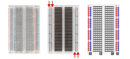
Breadboards (Figure 1) are small boards that are commonly used for circuit prototyping. They allow the circuit’s components to be connected without making permanent connections. The red and blue strips on the sides of the board (sections A and D) are called power rails and are connected down the board, usually used for powering and grounding. The non-colored rows between the power and ground strips (sections B and C) are connected across and are usually used for making the connections between components. Sections B and C are not connected to each other across the bridge in the middle of the board.
DC (Direct Current) Voltage Sources
DC voltage sources are used to power circuits because they have a voltage difference across their terminals. DC voltage sources are usually batteries (e.g. AA, AAA). Arduino boards can be powered by a battery, a USB cable, or an AC adapter. When the Arduino is powered, it can be used as a 5V DC voltage source.
Resistors
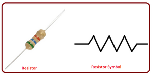
Resistors (Figure 2) are components that reduce the current flowing through a circuit and convert the excess current to thermal energy. They are one of the most common components in electrical circuits. Resistors are mainly used to limit the current flowing through a component. For example, when connecting an LED to a battery, a resistor helps limit the circuit to ensure the LED is not damaged.
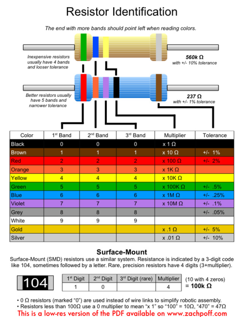
Resistors are color coded to indicate their resistance in ohms (Figure 3). They are not polarized, meaning the orientation of the resistor does not affect the circuit.
Push-Buttons and Switches
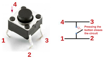
Push-buttons and switches (Figure 4) are mechanical devices that interrupt or divert current. Basic push-buttons are polarized while basic switches are not.
Diodes
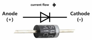
Diodes allow current to pass in only one direction. The anode is the positive terminal of the diode, and the cathode is the negative terminal. Diodes can also be used to amplify signals (Figure 5).
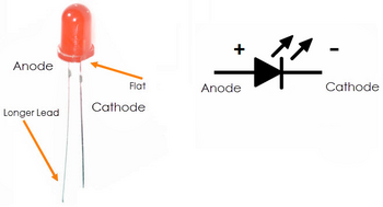
A light emitting diode (LED) is a small electric light that uses low voltage and current (Figure 6). The longer lead of an LED is the anode, and the shorter lead is the cathode. The orientation of an LED is important since they are polarized. Most LEDs also require a resistor because they will burn out almost instantly when they encounter high current.
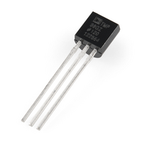
A TMP36 sensor (Figure 7) uses the voltage-temperature relationship of diodes to measure temperature. The voltage across the diode of the sensor will change proportionally to the temperature. The output voltage can then be converted to a temperature reading.
Microcontrollers
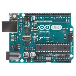
A microcontroller is an inexpensive, programmable computer without any peripherals, such as a mouse, keyboard, or screen. Microcontroller boards have direct access to the input and output pins of their processing chips so that the user can directly read from sensors and perform actions. Microcontrollers perform specific functions in household appliances, medical devices, cars, and other systems and devices. Arduino boards (Figure 8), which use a microcontroller, were designed to be easily programmed and assembled into larger projects. These boards come in many shapes and sizes, and some contain additional features, such as WiFi or Bluetooth connectivity. Different boards can also have different features, such as a higher processing speed and more memory.
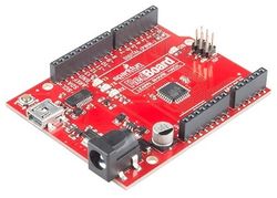
This lab will use an Arduino UNO board created by SparkFun called a RedBoard (Figure 9).
Arduino Hardware
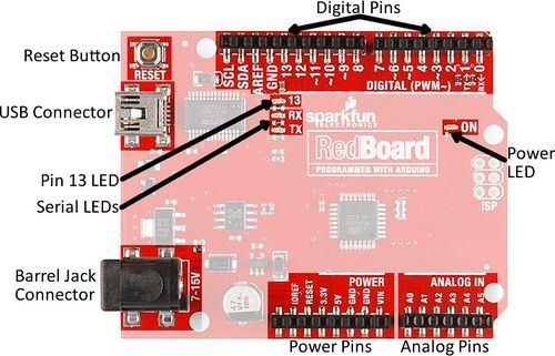
All Arduino boards have a general layout that is similar to that shown in Figure 10. Not all the sections and pins will be used in this lab or for the Semester Long Design Projects.
- Reset Button: Restarts the board
- USB Connector: Provides power and connects it to the computer
- Pin 13 LED: Usable LED without making an LED circuit
- Serial LEDS: Shows if the Arduino is transmitting or receiving data from pins 0, 1, or the USB connection
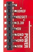
The power pins are used to supply voltage to other pins, and are also used to ground pins (Figure 11).
- 3.3V: Usually used to power low-voltage sensors
- 5V: Uused to power circuits
- GND: Ground pin, 0V
- VIN: Voltage-in can be used to power the board using a battery or other external voltage source
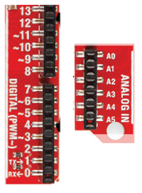
The digital and analog pins are used for input and output commands to the microcontroller and electrical components (Figure 12). They can be used with both analog and digital devices, as the Arduino board converts analog inputs to a digital input.
- A0-A5: Identical analog pins that can read sensors or control analog devices. Analog pins can read/write values from 0 to 1023
- Digital Pins 0-1: Transmitter and receiver pins. Do not use these pins for this lab
- Digital Pins 2-12: Digital pins that switch between HIGH states and LOW states. Can only read/write values HIGH or LOW, unlike analog pins that allow a greater range of values
- Digital Pin 13: Connected to the onboard LED, use it only as an input pin
The Arduino IDE (Integrated Development Environment)
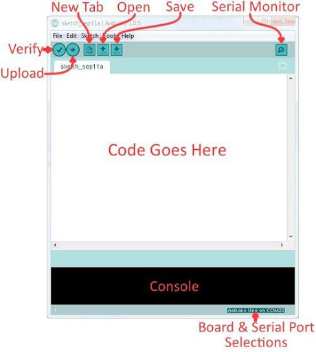
Arduino IDE is a program that can be used to edit, compile, and upload code to a supported microcontroller. Figure 13 shows a screenshot of the program’s interface.
- Verify: Checks code for errors and points to the errors
- Upload: Verifies code and uploads it to the Arduino board
- Console: Shows errors found in the hardware
- Serial Monitor: Sends messages to and receives messages from the board
Arduino Programming
The Arduino programming language is based on C/C++, but it is designed to be simpler and easier to learn. The intuitive way to think about programming is like building with LEGO blocks: certain rules must be followed and different building blocks can be used to build bigger parts.
Every line must end with a semicolon (;) unless it is a conditional, loop, or function. Comments start with two backslashes (//). Comments are text that the program ignores and are used to label and explain code.
Arduino Programs
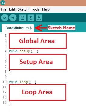
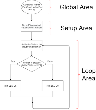
Programs written in Arduino are called sketches. A basic sketch can be broken up into three different areas: global, setup, and loop. These areas are pictured in Figure 14.
- Global: Contains constants and imported libraries
- Setup: Function runs once at start of the program. Setup function often used to activate pins and sensors in the program
- Loop: Function runs continuously after Setup function. Code in a loop function will continue to run until Arduino loses power. Function often in most of the program to read sensors and switch pins HIGH or LOW
Datatypes
Datatypes are the different kinds of data values that can be used, manipulated, and stored using C++. The most basic and widely used datatypes were shown in Table 1.
| Datatype | What It Stores (Examples) | Default Value | Notes |
|---|---|---|---|
| True value (1, HIGH) or false value (0, LOW) |
0, FALSE, LOW | - | |
| Integer number (e.g. -5, 15, 1047) | 0 | Positive or negative | |
| Decimal number (e.g. -0.5, 123.77) | 0 | Positive or negative | |
| Single character (e.g. ‘c’, ‘A’, ‘5’, ‘?’) | Indeterminate | Enclosed in single quotes | |
| Sequence of characters (e.g. “Hello World!”, “10”, “157+5”) | Empty (“”) | Enclosed in quotes |
Operators
Operators perform operations on variables and constants. The results of these operations are usually stored in a variable. Table 2 displays common operators.
| Operator | What it Does | Notes |
|---|---|---|
| = | Assigns a value to a variable | - |
| + | Adds two or more values | - |
| - | Subtracts two or more values | - |
| * | Multiplies two or more values | - |
| / | Divides two or more values | - |
| ++ | Increment by 1 | Usually used in loops |
| -- | Decrement by 1 | Usually used in loops |
| == | Checks if two values are equal | Usually used in conditionals |
| != | Checks if two values are not equal | Usually used in conditionals |
| > or < | Less than, greater than comparison | Usually used in conditionals |
| <= or >= | Less than, greater than, or equal to comparison | Usually used in conditionals |
| && or || | Boolean AND or Boolean OR ssed to cascade multiple Boolean operations | Usually used in conditionals |
Constants and Variables
Constants and variables (Figure 15) hold data according to their datatype. They must be given a name so they can be referred to later. Constants hold data that will not change while a program is running. Constants usually contain pin numbers or sensor threshold values. Variables contain data that will change while a program is running. Variables usually contain sensor values and other values that must have mathematical operations done on them. Figure 15 shows how to create different constants and variables.
Conditional Statements
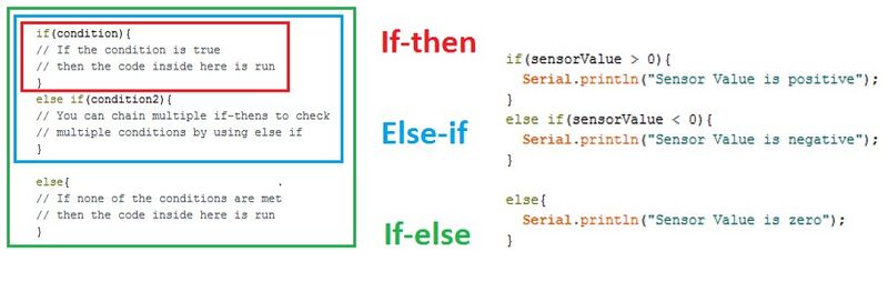
Conditional statements (Figure 16) run code enclosed by their curly brackets when a condition is met.
Loops
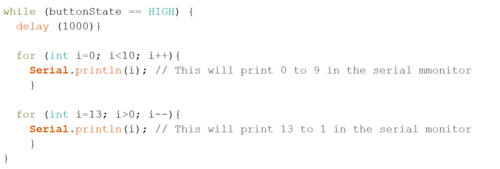
Loops run the code enclosed by their curly brackets a specific number of times or until a condition is met.
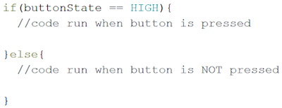
While loops are used to perform a task until a condition is met. In Figure 17, the while loop runs only if the state of the button is HIGH. When the state of the button becomes LOW, the while loop will stop running.
Commonly Used Functions
Table 3 shows commonly used functions in the Arduino IDE that are specifically used to work with the digital and analog pins of the board.
| Function | What it Does |
|---|---|
| pinMode(pin, mode) | Sets a pin as an input or output |
| digitalWrite(pin, value) | Sets a digital output pin to HIGH or LOW |
| digitalRead(pin) | Reads a digital input pin as HIGH or LOW |
| analogWrite(pin, value) | Sets an analog output pin to a value 0-1023 |
| analogRead(pin) | Reads an analog output pin as a value 0-1023 |
| delay(milliseconds) | Pauses program for a certain amount of time |
| Serial.print(value) | Prints the value (variable) to the Serial Monitor |
Heat and Heat Transfer
Heat is a form of energy. Heat can be beneficial, and it can be destructive. For example, the heat created by the combustion of fossil fuels in a combustion engine or the heat generated by the friction between parts of an engine in contact can destroy an engine. A heating, ventilation, and air conditioning (HVAC) system in a home keeps the home warm at cooler temperatures and cooler at higher temperatures. Many systems and devices use components and materials that are designed to remove heat from the system or retain heat in the system.
Heat transfer is the process of thermal energy moving from one body to another as a result of a temperature difference. Temperature is the measure of the average kinetic energy of atomic motion. The faster the atoms are moving, the higher the temperature. The main mechanisms of heat transfer are conduction, convection, and radiation.
Conduction occurs when there is a temperature difference within a solid body or between solid bodies in contact. During conduction, energy (heat) will flow from the region of higher temperature to the region of lower temperature. Imagine a metal rod that is heated at one end. The atoms of the rod collide at the point where the temperature differs, transferring energy until the temperature of the rod becomes uniform.
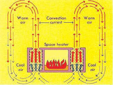
Convection is the transfer of heat within a fluid medium (fluids consist of gasses and liquids). Convection can occur as natural or forced convection. Forced convection (Figure 19) occurs when the main mechanism for heat transfer is due to an outside force causing the fluid to move. Natural convection results from the natural difference in density between fluids, causing a liquid or gas to rise.
Radiation is the process by which energy in the form of electromagnetic radiation is emitted by a heated surface in all directions. It does not require an intervening medium to carry it. The heating of the Earth by the Sun is an example of heat transfer by radiation. Electromagnetic radiation is a means of energy transfer that occurs when an atom absorbs energy. This electromagnetic wave can propagate as heat, light, ultraviolet, or other electromagnetic waves depending on the type of atom and the amount of energy absorbed.
Color is a property of light. When an object appears white, it virtually reflects all the electromagnetic waves coming to it while a black object absorbs the waves. Color (reflectivity) should be considered when choosing materials for thermal insulation.
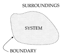
The container that will be built in the lab is a thermodynamic system (Figure 20), which is a part of the Universe separated from the surroundings by an imaginary boundary. There are three types of systems: open systems, closed systems, and isolated systems.
Open systems allow the transfer of mass and heat. For example, an open pot of boiling water is an open system. It exchanges heat and water vapor with the air around it. If collected, the water vapor can be condensed back to liquid water that has some mass.
Closed systems only allow heat to be transferred to the surroundings. A hermetically sealed bottle of soda is a closed system. If placed in a hot environment, it absorbs energy in the form of heat, but the amount of liquid within does not change.
Isolated systems do not interact with the surroundings at all. No exchange of heat or mass is possible. An ideal Thermos® is an isolated system. If hot chocolate is poured inside a Thermos, the same amount at the same temperature will be poured out later. No such system can be fabricated, but they can be approximated.
Understanding how to minimize heat loss is the key to designing a successful insulating container. The first consideration is the materials chosen. Using materials that are poor conductors of heat, such as glass, will minimize heat loss. Plastic is also a poor conductor of heat. Foam cups are made of plastic that has tiny air bubbles suspended in it. Air is among the poorest conductors of heat. A vacuum, or the complete lack of air, is the best insulator of all. This is the principle employed in a Thermos® design.
The other important consideration in creating the container is its cost. Minimal design uses the fewest resources while maintaining the safety and efficacy of a product.
Materials and Equipment
- Arduino UNO microcontroller and USB cable
- Computer with Arduino IDE
- Breadboard
- Jumper wires
- Resistors
- 220 Ω
- 10 kΩ
- 2.2 kΩ
- LED
- Push-button
- Thermistor
Procedure
1. Building an LED Circuit and Button Circuit
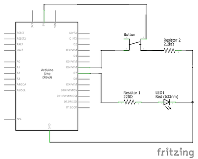
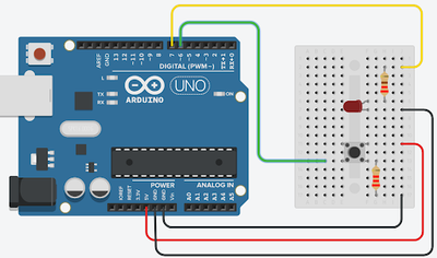
- A circuit using an LED and a button will be made in Part 1. The LED should be on when the button is pressed and off when the button is not pressed. The programming flowchart and circuit diagram are shown in Figure 21.
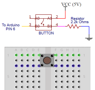
- Before breadboarding the circuit, look at the bottom side (pin side) of the button to determine which pins are connected. Note which pins are for power, ground, and digital input into the Arduino. There is a wire internally connecting the pins across the sides of the push-button (Figure 23). Pins 1 and 2 are connected, and pins 3 and 4 are connected. Make sure the button straddles the break in the breadboard.
- Breadboard the circuit diagram in Figure 24. Remember, since LEDs are polarized, their orientation matters. The shorter leg of the LED should be connected to the same row as GND. The 220 Ω resistor for the LED is needed, otherwise too much current would flow and the LED will burn out. The 2.2k Ω resistor for the button is needed to get a stable input. Make sure the correct resistor is used for both the LED and the button.
- Write the Arduino program to implement the flowchart. Include comments explaining what the code is doing. The code must have comments to be approved by a TA
- First start a new sketch in the Arduino IDE
- Open the Arduino IDE
- Plug the Arduino/RedBoard into the computer
- In the Arduino IDE toolbar, go to Tools > Board > Select Arduino/Genuino Uno
- In the toolbar, go to Port and select the correct port
- In the Global Area, create the constants used to hold the pin numbers for the button and the LED.
- In the Setup Area, use pinMode() to set up the LED and Button. The LED will be set to OUTPUT since it will be controlled by the program. The button will be set to INPUT since the program will receive data from the button.
- In the Loop Area, use digitalRead(), digitalWrite(), and a conditional to write the code that controls the button
- Create a variable named buttonState, that will hold the input from the button
- Use digitalRead() to set the buttonState variable to the current state of the button
- Set up the conditional statement that will be used to control the LED. In this code, the conditional is controlled by the button state.
- Use digitalWrite() to control the LED. Remember, we want the LED to be on when the button is pressed, and off otherwise
- This line will turn the LED on
- This line will turn the LED off
- This line will turn the LED on
- Create a variable named buttonState, that will hold the input from the button
- First start a new sketch in the Arduino IDE
2. Prototyping a Thermal Insulation Device
Competition Rules
The following rules must be observed at all times during the competition. Violation of any of these rules will result in disqualification.
- The placement of the thermistor with respect to the lid may not be changed
- The thermal insulating device may not be held while testing
- External heat sources are prohibited
- The jar of beeswax must be inside the container within 30 seconds of it being received
- The jar of beeswax cannot be returned (no restarts)
- A minimum of $0.40 must be used in the design of the insulating device
The competition will be judged by the minimal design ratio (MDR) (2) of the design. The design with the lowest MDR wins
(2)
In (2), IC is the insulating capacity, Cost is the cost of the container, TR is the temperature of the room, and TF is the final temperature read by the thermistor. Ask a TA for the room temperature
The insulating container will be built using the materials in Table 4. Select the materials carefully. Consider their cost and their use as an insulator. Review the competition ratio before purchasing materials
| Material | Unit | Cost Per Unit |
|---|---|---|
| Large foam cup | 1 | $0.50 |
| Lid | 1 | $0.25 |
| Pack of clay | 1 bag | $0.20 |
| Wool fabric | 2 pieces | $0.10 |
| Cotton balls | 3 balls | $0.05 |
| Popsicle sticks | 1 | $0.01 |
| Paper cup | 1 | $0.40 |
| Styrofoam pieces | 5 | $0.05 |
| Tape | 1 ft | $0.10 |
| Aluminum foil | 1 ft2 | $0.30 |
| Plastic wrap | 1 ft2 | $0.02 |
NO RETURN POLICY: When calculating cost, ALL materials requested must be included, even if they were not used. Choose the materials carefully to avoid increasing the cost unnecessarily.
3. Competition Procedure
Building a Thermistor
Using the Arduino, the temperature change of the hot wax will be recorded over 10 minutes. The Arduino will read the temperature through the thermistor and print the values into the serial monitor.
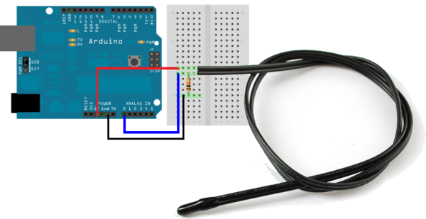
- Carefully remove the existing circuit and wire the circuit according to the configuration in Figure 28. A 10 kΩ (Brown, Black, Orange) resistor should be used. Make sure that pin A0 is used, and the circuit is powered to 5V and grounded.
- Download the Arduino Program to be used to operate the thermistor.
- There are missing components in the code. Read through the comments and insert code where necessary. After the program is completed and uploaded, open the Serial Monitor to check if the readings are correct (should be at or near 70 °F). Keep the circuit intact since it will be used to measure the temperature of the wax.
- The Arduino should be taking a temperature reading every 30 seconds. The analog voltage value read through pin A0 should then be converted to degrees Fahrenheit. The temperature reading should be printed to the Serial Monitor along with the seconds timestamp of the reading.
Insulating Device Design
- Analyze the materials and consider the design options, keeping in mind the lab's specifications. Make preliminary sketches during this process.
- Sketch the design. Label the drawings clearly. Prepare a price list and write down the total cost for the insulating container based on the materials chosen. Receive approval of the design sketch from a TA.
- Build the insulating device based on the completed sketch. The TA will provide the materials needed for the design. If the design is modified during construction, note the changes and describe the reasons for them. If the modifications required more materials, update the price list and obtain approval.
Competition
- Have a TA verify the fixed Arduino code. Run the program for approximately 30 seconds to obtain an average room temperature. The data from the Arduino can be seen in the Serial Monitor on the top right corner of the Arduino IDE.
- Stop the program after 30 seconds and check to ensure that the data was collected. Record the average room temperature.
- The TA will bring the heated wax. Place the lid with the thermistor attached over the top of the wax. Be sure the top of the container is loosely covered with the lid.
- Do not adjust the thermistor from its position in the lid. Do not screw on the lid, just place it over the container. Warning: Be careful! The melted wax is hot!
- Restart the Arduino program. Once the temperature readings stop increasing, start timing the 10 minute run.
- The data from the thermistor will allow for further analysis. The Arduino data from the Serial Monitor will be used to calculate the insulating capacity (IC) for the competition ratio. DO NOT CLOSE OUT OF THE SERIAL MONITOR WINDOW. After 10 minutes from the time the temperature readings stop increasing, copy and paste the data from the Serial Monitor into a Microsoft Excel file.
4. Data Analysis
- The data pasted from the Serial Monitor into Excel is not correctly separated into columns. To present the data in the correct format, highlight all the data, and go to the Data tab and select “Text to Columns”.
- In the Text-to-Columns wizard, select Delimited as the data type and click Next. Then select “Comma” as the delimiter, and hit “Finish”. Ensure that the data has been separated into two separate columns.
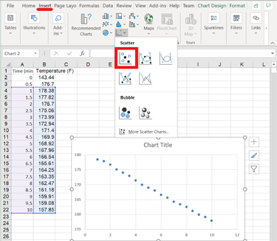
- Create a graph of the data using the X, Y Scatter template. First, select the data starting from the where the temperature readings stop increasing (example below). Next go to the Insert tab, and click on the first Scatter option under the Charts group. This should create a new scatter plot, as seen below.
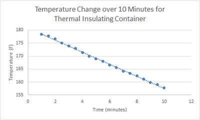
- Next add axis labels and a trendline. First click on the graph, and then the green “+” icon next to it. Then, check off “Axis Titles, Chart Titles, and Trendline”. Click on the added labels to edit the text. When finished, the graph should look similar to Figure 29. Figure 29: Temperature vs. Time Graph of the Thermal Insulation Device
- Calculate the insulating capacity (IC) of the design. This will be done using the trendline equation. Right-click on the trendline and select “Format Trendline”. On the “Trendline Options” tab, ensure that the trendline is linear. Select the “Display Equation on Chart" option. The slope of this linear equation is the IC.
- Give the IC, final temperature, and total cost to the TA to enter the design's performance into the competition score sheet and calculate the MDR.
The lab work is now complete. Please clean up the workstation. Return all unused materials to a TA.
Assignment
Note: Part 2: Thermal Insulation Device Competition will be included in both lab report and team presentation. Part 1: Building an LED and Button Circuit DOES NOT need to be included in the lab report and team presentation.
Individual Lab Report
Follow the lab report guidelines laid out in the EG1004 Writing Style Guide in the Technical Writing section of the manual. Use the outline below to write this report. The LED and button circuit procedure does not need to be discussed.
- Abstract
- Briefly summarize the lab exercise. Include the competition results
- Introduction
- Discuss prototyping, the hardware and software components used in the lab, heat and heat transfer, all elements of the competition, and the design strategy and impact of rules, materials, and ratio on design strategy
- Procedure
- Materials
- Describe the steps taken in the competition exercise in sufficient detail so that another person could follow the description and replicate the results
- Data/Observations
- Present and discuss all data collected during the exercise
- Conclusion
- Analyze the competition results using the data from the competition
- Describe how the design’s performance could be improved. Recalculate the ratio to prove that design modifications would improve performance
- Discuss what factors could affect the MDR and IC
- Describe the Temperature vs Time graph. Discuss potential factors that could affect the graph readings that were recorded and the shape of the graph
- Contribution Statement
Note: It is not unusual to experience instrumentation errors in this lab, leading to incorrect temperatures being recorded. Be sure to read How to Handle Unusual Data in the manual to learn how to handle this.
Remember: Lab notes must be taken. Experimental details are easily forgotten unless written down. EG1004 Lab Notes paper can be downloaded and printed from the EG1004 Website. Use the lab notes to write the Procedure section of the lab report. At the end of each lab, a TA will scan the lab notes and upload them to the Lab Documents section of the EG1004 Website. One point of extra credit is awarded if the lab notes are attached at the end of the lab report. Keeping careful notes is an essential component of all scientific practice.
Team PowerPoint Presentation
Follow the presentation guidelines laid out in the EG1004 Lab Presentation Format in the Technical Presentations section of the manual. When preparing the presentation, consider the following points.
- What is the importance of prototyping and using Arduino?
- What is the importance of minimal design?
- How are materials selected in prototyping?
- Why is it important to minimize heat loss?
- What is the importance of the automation of proper data collection methods?
- How can the design be improved?
References
Poff, Zach. (n.d.). “Resistor Color Code Chart.” Accessed August 11, 2021 from zachpoff.com
| ||||||||

