Difference between revisions of "Prototyping with Microcontrollers and Sensors"
Jbringardner (talk | contribs) |
Jbringardner (talk | contribs) |
||
| Line 99: | Line 99: | ||
[[Image:breadboard.jpg|500px|thumb|center|Figure 1: Breadboard Connections]] | [[Image:breadboard.jpg|500px|thumb|center|Figure 1: Breadboard Connections]] | ||
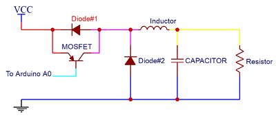
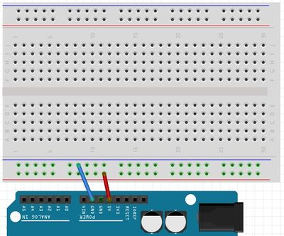
As seen in the Figure 1, the internal connections of a breadboard are very specific. Sections A and D depict how the power rails stretch the length of the board. This is where the 5V and GND connections from the Arduino can be used to power the circuits. Sections B and C are where circuits are built. Below is an example of how to wire a breadboard from a schematic. Do NOT build this circuit, just follow along. See the lab 5 '''''[https://stream.nyu.edu/media/EG+1003+Lab+5A+NI+ELVIS+Tutorial/1_36717xpx NI ELVIS Tutorial Video]''''' on the EG manual for more information on how to use breadboards. | As seen in the Figure 1, the internal connections of a breadboard are very specific. Sections A and D depict how the power rails stretch the length of the board. This is where the 5V and GND connections from the Arduino can be used to power the circuits. Sections B and C are where circuits are built. Below is an example of how to wire a breadboard from a schematic. '''''Do NOT build this circuit, just follow along'''''. See the lab 5 '''''[https://stream.nyu.edu/media/EG+1003+Lab+5A+NI+ELVIS+Tutorial/1_36717xpx NI ELVIS Tutorial Video]''''' on the EG manual for more information on how to use breadboards. | ||
# Circle all the wire nodes in the schematic, in this case they are color coded. Every node will be a row used on the bread board. | # Circle all the wire nodes in the schematic, in this case they are color coded. Every node will be a row used on the bread board. | ||
| Line 114: | Line 114: | ||
# Finally, connect a wire to the row that connects the diode(#2), capacitor, and resistor (color coded in the schematic in dark blue) and connect A0 to the appropriate row (color coded in the schematic in light blue). | # Finally, connect a wire to the row that connects the diode(#2), capacitor, and resistor (color coded in the schematic in dark blue) and connect A0 to the appropriate row (color coded in the schematic in light blue). | ||
#: [[Image:step5.jpg|thumb|center|400px]] | #: [[Image:step5.jpg|thumb|center|400px]] | ||
As seen in the figure, there are 5 colored connections in the original circuit and only 5 rows were used on the breadboard. Note how the diodes are oriented! | As seen in the figure, there are 5 colored connections in the original circuit and only 5 rows were used on the breadboard. Note how the diodes are oriented! | ||
=== The Arduino IDE === | === The Arduino IDE === | ||
Revision as of 11:51, 1 September 2016
Objectives
The objective of this lab is to utilize the basics of electronics, the Arduino board, and the Arduino IDE (Integrated Development Environment). The Arduino IDE will be used to program the Arduino board. These skills will be used for several hands-on tasks including programming the Arduino to control an LED with a button, take readings with a temperature sensor, and design a basic prototype for a product.
Overview
Electricity
To put simply, electricity is the movement of electrons. Electrons flow through a conductive wire when there is a difference in charge between two points in the wire. This flow of electrons is called electrical current and it is measured in Amperes (A). Due to convention, electrical current flows opposite of the electrons. The difference in charge is called electrical voltage and it is measured in Volts (V). Another way to think about electrical voltage is to picture it as “electrical pressure,” analogous to water pressure. If there is a tank full of water (electrons) and a hole is poked in it, water will flow (electrical current flowing), due to the water pressure (electrical voltage) inside the tank. Finally, there are certain materials that resist that flow of electrons. This property is called electrical resistance and it is measured in Ohms (Ω). Resistors are electronic devices that are specifically designed to resist the flow of electrical current.
There exists a mathematical relationship between current, voltage and resistance which is characterized by Ohm’s Law. This relationship is detailed below, where V is the voltage across a resistor, I is the current flowing through a resistor and R is the resistance of the resistor.
Failed to parse (MathML with SVG or PNG fallback (recommended for modern browsers and accessibility tools): Invalid response ("Math extension cannot connect to Restbase.") from server "https://wikimedia.org/api/rest_v1/":): {\displaystyle V=I*R}
Electronic Components
There are several basic electronic components used to build simple circuits. Some of these components are polarized which means the way they are connected matters! Another way of thinking about it is that some components are symmetrical while others are not.
DC (Direct Current) Voltage Sources
DC Voltage Sources are used to power circuits because they have a voltage difference across their terminals. DC Power Sources are usually batteries (AA, AAA, etc). Arduino boards can be powered by a battery, a USB cable, or an AC adapter. When the Arduino is powered, it can be used as a 5V DC voltage source. They ARE polarized.
Resistors
Resistors are components that reduce the amount of current flowing through a circuit. Resistors convert the excess current to thermal energy. Resistors can be used to control the voltages and currents of circuits. Resistors are color coded with what resistance they are. They are NOT polarized.
Capacitors
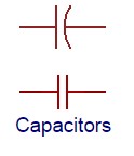
Capacitors are components that can store energy in an electrical field and then dissipate it at a later time. Capacitance is a measure of how much charge a capacitor can store and it is measured in Farads (F). Capacitors resist voltage changes by supplying or drawing current. They are SOMETIMES polarized.
Inductors
Inductors are components that can store energy in a magnetic field and then dissipate it at a later time. Inductance is a measure of how much energy an inductor can store and it is measured in Henrys (H). Inductors resist current changes by dropping or increasing the voltage across itself. They are NOT polarized.
Push-buttons and Switches
Push-buttons and switches are mechanical devices that interrupt or divert current running through them. Basic push-buttons and are polarized while basic switches are not.
Diodes and Transistors (BJT/MOSFETS)
Diodes are components that allow current to only pass in one direction.
MOSFETs are electric components that act as electrically controlled switches. They can also be used to amplify signals. They ARE polarized.
Light Emitting Diodes
LEDs are small electric lights which use low voltages and currents. The orientation of the LED is important since it acts like a diode and only allows current to flow in one direction. Most LEDS also require a resistor (typically 470 Ω) in series with them because they will burn out almost instantly when they encounter high current. They ARE polarized.
IC (Integrated Circuit) Chips
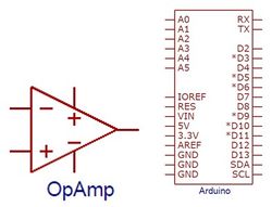
IC chips contain small electrical circuits inside them to usually do one specific purpose. They can come in all shapes, sizes and specifications. Common IC chips that are used include comparators (they compare two different voltages), op-amps (they amplify low voltage signals) and timers (they switch between high and low voltages quickly to time other devices). The blank rectangular components on the Arduino are all IC chips. They ARE polarized.
Analog vs. Digital Signals
An electrical signal is any quantifiable quantity that can carry information using electricity. Digital signals have two discrete states: LOW and HIGH. Generally speaking, most devices output a voltage level of 0V when the signal is LOW and 5V when the signal is HIGH. For example, a comparator can compare two signals and output 0V if the first signal is greater than the second or output 5V is the second signal is greater than the first.
Analog signals, on the other hand, can theoretically take on an infinite amount of voltage values. In reality, analog signals consist of a large range of numbers which are mapped to corresponding voltage values. For example, the Arduino can output a range of analog values from 0-1023 (corresponding to 0V-5V). This means the value 255 will have a voltage value of ~1.246V while the value 781 will have a value of ~3.817V. Many electronic components are inherently analog.
Microcontrollers
A microcontroller is a cheap, programmable computer without any of the peripherals such as a mouse, keyboard, or screen. Microcontroller boards have direct access to the input and output pins of its processing chip so that the user can directly read from sensors and perform actions. Microcontrollers are present in many electrical appliances like microwaves.
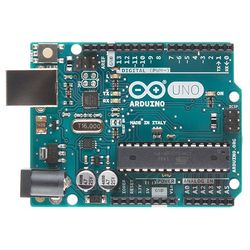
Arduino boards were designed to be easily programmed and assembled into larger projects. These boards come in many shapes and sizes and some contain additional features such as WiFi or Bluetooth connectivity. Different boards can also have different features such as processing speed and memory size.
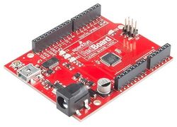
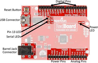
This lab will be using an Arduino UNO board created by SparkFun called a RedBoard.
Arduino Hardware
Reset Button: Restarts the Board
USB Connector: Provides power and connect it to the computer
Pin 13 LED: Usable LED without making an LED circuit
Serial LEDS: Shows if the Arduino is transmitting or receiving data from pins 0, 1 or the USB connection
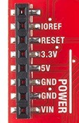
Power Pins
3.3V: Usually used to power low-voltage sensors
5V: Most common power pin used to power circuits
GND: Ground pin which is 0V
VIN: Voltage-In can be used to power the board using a battery
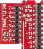
I/O Pins
A0-A5: Identical analog pins that can be used to read sensors or control analog devices. Pins A0-A3 are more stable than A4-A5
Pins 0-1: Transmit and Receive pins, don’t use these pins for this lab
Pins 2-12: Digital pins that can be switched between HIGH states and LOW states
Pin 13: Connected to the on-board LED, use it only as an input pin
Building Circuits on a Breadboard
Breadboards are small boards that are commonly used for circuit prototyping. They allow the connection of components that were discussed previously without making permanent connections.
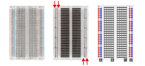
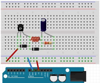
As seen in the Figure 1, the internal connections of a breadboard are very specific. Sections A and D depict how the power rails stretch the length of the board. This is where the 5V and GND connections from the Arduino can be used to power the circuits. Sections B and C are where circuits are built. Below is an example of how to wire a breadboard from a schematic. Do NOT build this circuit, just follow along. See the lab 5 NI ELVIS Tutorial Video on the EG manual for more information on how to use breadboards.
- Circle all the wire nodes in the schematic, in this case they are color coded. Every node will be a row used on the bread board.
- Connect the 5V and GND pins to the power rails.
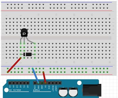
- Start with components connected to Vcc (5V) (the red node). In this example, the transistor and the diode(#1) have to connect to 5V so plug one end of each to the same row and then connect a wire from the power rail to that row.
- Since the other ends of the diode (#1) and transistor (color coded in the schematic in red) connect together as well, put them both into a second row. The middle pin of the transistor goes into a row by itself because it need to go to the Arduino later on.
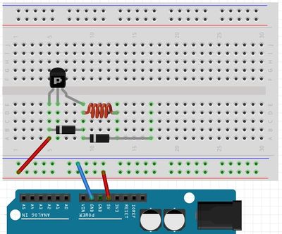
- The other components that connect to that second node are (color coded in the schematic in pink): the inductor and another diode (#2). Plug one end of those components into the second row. Then, plug the other ends of the inductor and diode(#2) into separate new rows since they connect to different nodes.
- The only components remaining are the capacitor and resistor (color coded in the schematic in yellow) which plug into the rows that are designated for those nodes.
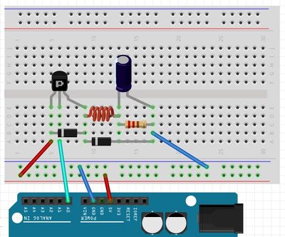
- Finally, connect a wire to the row that connects the diode(#2), capacitor, and resistor (color coded in the schematic in dark blue) and connect A0 to the appropriate row (color coded in the schematic in light blue).
As seen in the figure, there are 5 colored connections in the original circuit and only 5 rows were used on the breadboard. Note how the diodes are oriented!
The Arduino IDE
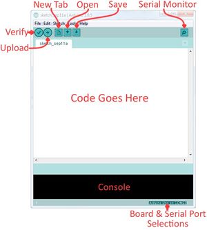
The Arduino IDE is a program that can be used to edit, compile, and upload code to a supported microcontroller. Figure 2 is a screenshot of the program:
Verify: checks code for errors and points to where the errors occurred after it finishes. Upload: verifies code and then uploads it to the Arduino board if there are no errors.
Console: shows any errors the software found in hardware.
Serial Monitor: a tool used to see how a program is running. It’s like a multimeter for the program.
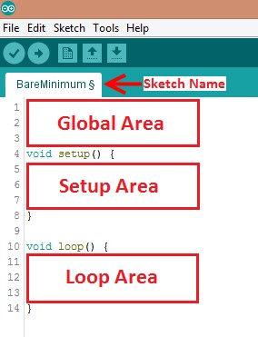
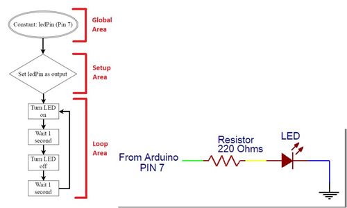
Programs written in Arduino are called sketches. A basic sketch can be broken up into 3 different areas: global, setup and loop; these areas are pictured below.
Global: constants and imported libraries go here.
Setup: activate the pins and sensors used. This code only runs once.
Loop: the code that runs continuously such as reading sensors and turning pins HIGH or LOW.
Arduino Programming
The Arduino programming language is based on C/C++, but it is designed to be simpler and easier to learn. The most intuitive way to think about programming is like building with LEGO blocks: certain rules must be followed and different building blocks can be used to build bigger parts.
General
- Every line must either end with a semicolon ‘;’ unless it’s a conditional, loop, or function
- Comments start with a //
- Comments are text that the program ignores
- Used to label and explain code
Datatypes
Datatypes are the different kinds of data values that can be used, manipulated and stored using C++. The table below includes the most basic and widely used datatypes.
| Datatype | What it stores (examples) | Default value | Notes |
|---|---|---|---|
| Boolean | A true value (1, TRUE, HIGH) or a false value (0, FALSE, LOW) |
0, FALSE, LOW | - |
| int | An integer number (-5, 15, 1047, etc.) | 0 | Can be positive or negative |
| double | A decimal number (-0.5, 123.77, etc.) | 0 | Can be positive or negative |
| char | A single character (‘c’, ‘A’, ‘5’, ‘?’, etc.) | Indeterminate | Must be enclosed in single quotes |
| string | A sequence of characters (“Hello World!”, “10”, “157+5”, etc.) |
Empty (“”) | Must be enclosed in double quotes |
Operators
Operators perform operations on variables and constants. The results of these operations are usually stored in a variable. The table below includes common operators.
| Operator | What it does | Notes |
|---|---|---|
| = | Assigns a value to a variable | |
| + | Adds two or more values | |
| - | Subtracts two or more values | |
| * | Multiplies two or more values | |
| / | Divides two or more values | |
| ++ | Increment by 1 | Usually used in loops |
| -- | Decrement by 1 | Usually used in loops |
| == | Checks if two value are equal | Usually used in conditionals |
| != | Checks if two value are not equal | Usually used in conditionals |
| > or < | Less than/Greater than comparison | Usually used in conditionals |
| <= or >= | Less than/greater than or equal to comparison | Usually used in conditionals |
| && or || | Boolean AND or Boolean OR Used to cascade multiple Boolean operations | Usually used in conditionals |
Constants and Variables
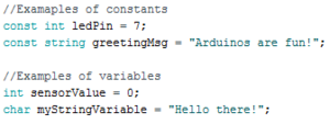
Constants and variables hold data according to their datatype. They need to be given a name so they can be referred to later. Constants hold data that will NOT change while a program is running. Constants usually contain pin numbers or sensor threshold values. Variables contain data that WILL change while a program is running. Variables usually contain sensor values and other values that need to have mathematical operations done on them. Below is an example of how to create different constants and variables.
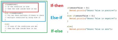
Conditional Statements
Conditional statements run code enclosed by their curly brackets when a condition is met.
Loops
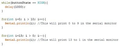
Loops run the code enclosed by their curly brackets a specific amount of times or until a condition is met.
While-loop
While-loops are used to perform a task until a condition is met
For-loop
For-loops are used when you want something to run a specific number of times. Although they seem complicated at first, the structure of most for-loops is the same. In the parenthesis, the first part sets a variable (usually ‘i’ for ‘index’) to a value used to begin a count, the middle is the condition when the loop stops, and the third part is where you increment or decrement the counting variable.
Commonly Used Arduino Functions
| Function | What it does |
|---|---|
| pinMode(pin,mode) | Sets a pin as an input or output |
| digitalWrite(pin, value) | Sets a digital output pin to HIGH or LOW |
| digitalRead(pin) | Reads an digital input pin as HIGH or LOW |
| analogWrite(pin, value) | Sets an analog output pin to a value 0-1023 |
| analogRead(pin) | Reads an analog output pin as a value 0-1023 |
| delay(milliseconds) | Pauses the program for a certain amount of time |
| serial.print(value) | Prints the value (variable) to the Serial Monitor. |
Product Evaluation
Product evaluation is a common task for an engineer and for companies. Sometimes the product evaluated will be a company's product, and sometimes companies will be evaluating a competitor's design. In either case, this evaluation will use a standard (an accepted value), determine an average, and calculate accuracy and precision.[1]
When taking measurements, the first step is to determine an average.
In this equation, Ap is the average, P1, P2, P3, ..., Pn are the results of the tests and N is the total number of tests performed.
The average is compared to the standard. Accuracy is a variable the must always be considered. The degree of accuracy required will allow the results to be verified. Engineers often work on projects that affect people's safety; it is critical that the solutions to the problems solved by technical professionals are accurate.
The comparison of the average to the standard is called accuracy, defined as Acc in the following equation:
Failed to parse (MathML with SVG or PNG fallback (recommended for modern browsers and accessibility tools): Invalid response ("Math extension cannot connect to Restbase.") from server "https://wikimedia.org/api/rest_v1/":): {\displaystyle Acc = \left|P_s - A_p\right|\,}
In this equation, Ps is the standard value, and Ap is the value measured. Accuracy is always a positive number, so use the absolute value in case Ps is less than Ap.
Precision is the repeatability of a result, or how close the results are to each other, defined as Prec in the following equation:
Failed to parse (MathML with SVG or PNG fallback (recommended for modern browsers and accessibility tools): Invalid response ("Math extension cannot connect to Restbase.") from server "https://wikimedia.org/api/rest_v1/":): {\displaystyle Prec = \left|P_{high} - P_{low}\right|\,}
In this equation, Prec is precision, Phigh is the highest data value and Plow is the lowest data value. Like accuracy, precision is always a positive number, so use an absolute value here as well.
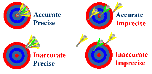
A product test can be accurate but imprecise, or precise but inaccurate (Figure 1). The goal is always the combination of accuracy and precision. In order for engineers to make a recommendation based on experimental test data, it is important to determine how a product compares to a standard. Engineers need these benchmarks to determine the quality of a product.
By determining the percent accuracy of an experiment, and comparing this percentage to a standard, it can be determined, based on experimental evidence, if the product has passed or failed. The equation for percent accuracy is:
In this equation, %Acc is the percent accuracy, Ps is the standard value, and Ap is the value measured.
Percent accuracy shows how precise a product is compared to the standard.
Calculating precision and percent accuracy and then comparing results to given tolerances determines the quality of the product.
Design Considerations
Carefully consider the inconsistencies of the sensors that are used in the lab and the needs of a reliable product.
- What is the accuracy and precision of the temperature sensor?
- How could this sensor be incorporated into a product?
Materials and Equipment
- Arduino UNO microcontroller and USB cable
- Computer with Arduino IDE
- Breadboard and jumper wire
- Resistors
- 220 Ohms
- 2.2k Ohms
- LED
- Pushbutton
- TMP36
Procedure
Starting a new sketch in Arduino
- Open the Arduino IDE
- Plug the Arduino/RedBoard into the computer
- In the Arduino IDE toolbar, go to Tools > Board and select “Arduino/Genuino Uno”
- Also in the Tools toolbar, select the correct port
Activity 1: Building an LED Circuit
- The first activity will be making a simple LED blinking circuit. The programming flowchart and circuit diagram are in Figure 3.
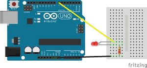
- First, wire the LED to the breadboard like in Figure 4. Remember, since LEDs are polarized, their orientation matters. The shorter leg of the LED should be connected to the same row as GND. The resistor is NECESSARY, otherwise too much current would flow and the LED will burn out!
- Now type the following code into a new sketch.
- The flowchart uses Digital Pin 7 on the Arduino as an output. Therefore, create a constant that holds the number 7 and in the setup area set Pin 7 as an output using pinMode. Then, turn the LED on by using digitalWrite, have a delay of one second, turn the LED off by using digitalWrite and then set another delay of one second.
- The LED circuit will be used in the next two activities. Do not deconstruct it.
Activity 2: Using a Button
- Activity 2 adds a button to the circuit from activity 1 and requires conditionals (think if-statement). The LED should be on when the button is pressed and off when the button isn’t pressed.
- Before you breadboard the circuit look at the bottom side (pin side) of the button to examine which pins are connected. There is a line connecting the pins that are wired together internally on each side. See the schematic below, pins 1 and 2 are connected, and pins 3 and 4 are connected.
- First, breadboard the circuit diagram in Figure 5 and sketch a flowchart of the program needed. Have a TA verify the flowchart.
- Write the Arduino program to implement the flowchart.
- Remember to create a constant that holds the pin number to which the button is connected and that the button will be a digital input. After the button constant, create an integer that will hold the button state:
- Within the loop function, you must check the state of the button (whether it is pressed or not pressed), using the following code:
Activity 3: Adding a Loop
- Activity 3 introduces a loop into the program so the LED flashes three times. Make sure to sketch a flowchart and have a TA verify it.
- Hint: Use a For-loop! The circuit does not need any modifications.
Activity 4: Reading from a Temperature Sensor
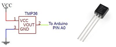
- For Activity 4 the Arduino will read analog values from a temperature sensor and print out the temperature to the Serial Monitor. Carefully disconnect everything plugged into the breadboard and Arduino. Then, breadboard the circuit in Figure 6.
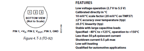
- The TMP36 is an IC temperature sensor. The specifications of most IC chips can be found online. Below is a picture of the pinout and the specifications of the TMP36. The sensor requires a positive voltage (Vs), a ground connection (GND), and an analog input connection (Vout) to read the temperature data. Use the +5 V pin from the Arduino board as your positive voltage connection.
- The output voltage can easily be converted to a temperature reading (in Celsius) by using a scale factor of 10 mV/°C. The Arduino should read the sensor every five seconds. Sketch a flowchart and have it verified by a TA before writing the program. Don’t forget to use an analog pin (Pin A0), convert the voltage reading and then print it out!
- Take 5 measurements of the room using the temperature sensor with one minute intervals. Use this data for the accuracy and precision measurements of your temperature sensor. TAs will provide the actual room temperature.
Activity 5: Arduino Resources and Example Projects
This lab has covered how to build simple circuits, program an Arduino microcontroller, and analyze sensor data. These are the basic building blocks for a project that performs a programmable action. An Arduino can be programmed to control a motor, write output to an LED or LCD screen, or send data wirelessly. Take a look at some of the resources below and brainstorm three sensors or output devices that may be needed for the SLDP.
Tabulation of Results
To decide if the product is ready to manufacture, arrange the data in a table designed to calculate its precision and accuracy. Remember it must pass all the tests at a rate of at least 80%.
| Original Design | Accuracy | %Acc | Precision | Tolerance |
|---|---|---|---|---|
| Temperature Reading |
The lab work is now complete. Please clean up the workstation. Return all unused materials to the TA. Refer to the Assignment section for the instructions needed to prepare the lab report.
Assignment
Individual Lab Report
Follow the lab report guidelines laid out in the page called Specifications for Writing Your Lab Reports in the Technical Communication section of this manual. The following discussion points should be addressed in the appropriate section of the lab report:
- Discuss the Arduino, electronics, and software used.
- Describe how the circuits were constructed.
- Calculate the accuracy, percent accuracy, and precision of the temperature sensor.
- Evaluate which sensors would be useful for your planned SLDP proposals.
- Research products on the market similar to your planned SLDP proposals. Evaluate that product and explain how your product will improve on existing capabilities.
Team PowerPoint Presentation
Follow the presentation guidelines laid out in the page called EG1003 Lab Presentation Format in the Introduction to Technical Presentations section of this manual. When preparing the presentation, consider the following points:
- What are some applications of Arduino and sensors?
- Why is accuracy and precision important when designing a product that relies on sensors?
- Why is product evaluation and improvement important?
References
- ^ Oakes, W.C., L.L. Leone, and C.G. Gunn, Engineering Your Future, MI: Great Lakes Press, 2002.
Example projects from Arduino users, http://playground.arduino.cc/Projects/ArduinoUsers
SparkFun Experiment Guide, https://learn.sparkfun.com/tutorials/sik-experiment-guide-for-arduino---v32/introduction-sik-redboard--sparkfun-mini-inventors-kit
| ||||||||
