Difference between revisions of "HIR Workshop"
| (44 intermediate revisions by 8 users not shown) | |||
| Line 1: | Line 1: | ||
= Objective = | = Objective = | ||
The objective of this workshop is to analyze and complete an incomplete house plan with an electrical plan, a plumbing plan, an extra floor, a roof, and additional utilities using Autodesk Revit. | The objective of this workshop is to analyze and complete an incomplete house plan with an electrical plan, a plumbing plan, an extra story (floor), a roof, and additional utilities using Autodesk Revit. | ||
= Overview = | = Overview = | ||
== Revit == | == Revit == | ||
'''Autodesk Revit''' is a Building Information Modeling (BIM) software used by architects, engineers, and contractors to plan, design, construct, and manage building and infrastructure designs. For architects, Revit is used to create floor plans, elevations, and 3D views in addition to rendering and animating the building design. For structural engineers, Revit is used to analyze and evaluate how well a building conforms to building and safety regulations. For mechanical, electrical, and plumbing (MEP) engineers, Revit allows coordination with architects and other engineers to design systems with all the architectural and structural components. For construction professionals, Revit is used to plan and understand construction methods, materials, and schedules. | |||
== Plumbing & Electrical Plans == | == Plumbing & Electrical Plans == | ||
In addition to other technical drawings, architects, engineers, and contractors require plumbing and electrical plans to accurately construct buildings. | In addition to other technical drawings, architects, engineers, and contractors require plumbing and electrical plans to accurately construct buildings. '''Plumbing plans''' show various plumbing fixtures, such as sinks, toilets, and showers, and the pipes connecting these fixtures to water sources and disposal systems. There are three main types of water systems: hot water, cold water, and sanitary water. Hot and cold water systems introduce filtered, ready-to-use water into the plumbing system while sanitary systems remove wastewater from the system and route this water to treatment facilities. Plumbing plans ensure that each component receives the right type of water and has adequate disposal of wastewater. | ||
'''Electrical plans''' show the electrical components within a building. These schematics include the electrical circuits within the system. Each electrical circuit is routed to a centralized panel board that houses circuit breakers and fuses, one for each electrical circuit. Electrical plans also show electrical outlets that have two main types: default and ground fault circuit interrupters (GFCI). GFCI outlets are mainly used near water sources as they help prevent water damage to circuits that can cause fatal accidents where current can be inadvertently directed away from the outlet and cause shock. Electrical plans direct the wiring of outlets and other appliances. | |||
== LEED Accreditation == | == LEED Accreditation == | ||
'''Leadership in Energy and Environmental Design (LEED)''' is an internationally used green building certification program developed by the U.S. Green Building Council. To receive LEED certification, building projects must satisfy prerequisites and earn points to achieve different levels of certification. The different categories for the LEED checklist correspond to principles of design, construction, and maintenance. The eight LEED categories with brief descriptions are: | |||
# Location and Transportation | # Location and Transportation | ||
## Diverse land use | ## Diverse land use | ||
| Line 48: | Line 48: | ||
## Sustainability not covered in other topics | ## Sustainability not covered in other topics | ||
# Regional Priority | # Regional Priority | ||
## Addressing region specific environmental, social equity, and public health priorities | ## Addressing region-specific environmental, social equity, and public health priorities | ||
== Third-Party Revit Components == | == Third-Party Revit Components == | ||
While Revit has a wide range of components, additional components can be downloaded from third-party websites and imported into existing Revit files. Common third-party websites include [https://new.bimobject.com/en-us/search?sort=trending BIMObject], [https://bimsmith.com BIMSmith], and [https://www.revitcity.com/downloads.php RevitCity]. These websites are continuously updated with new components. | While Revit has a wide range of components, additional components can be downloaded from third-party websites and imported into existing Revit files. Common third-party websites include [https://new.bimobject.com/en-us/search?sort=trending BIMObject], [https://bimsmith.com BIMSmith], and [https://www.revitcity.com/downloads.php RevitCity]. These websites are continuously updated with new components. Making an account with one of these sites will be extremely beneficial in the completion of both your project and this workshop. | ||
= Materials and Equipment = | = Materials and Equipment = | ||
* Autodesk Revit | * Autodesk Revit 2025 or newer | ||
= Procedure = | = Procedure = | ||
In this workshop, an electrical plan, a plumbing plan, designing and connecting multiple floors, and designing a roof will be completed. An incomplete two-floor house plan is provided to explore these skills. Download the incomplete two-floor house plan RVT file [ | In this workshop, an electrical plan, a plumbing plan, designing and connecting multiple floors, and designing a roof will be completed. An incomplete two-floor house plan is provided to explore these skills. Download the incomplete two-floor house plan RVT file [[Media:2025RevitWorkshop.zip | here]]. To avoid compatibility issues, use Autodesk Revit 2025 or a newer version. The file that is attached above is a .zip file. To extract the files you must download it, click on the folder once, then at the top ribbon click “Extract”. From there you will be able to open the relevant files to complete this workshop. | ||
== Plumbing Plan == | == Plumbing Plan == | ||
In this part, a plumbing plan will be created for one bathroom on the first floor. Understanding the implementation of a plumbing plan will be important for the completion of Benchmark B for the Housing in Revit (HIR) semester-long design project (SLDP). | In this part, a plumbing plan will be created for one bathroom on the first floor. Understanding the implementation of a plumbing plan will be important for the completion of Benchmark B for the Housing in Revit (HIR) semester-long design project (SLDP). | ||
# Open | # Open the file above. | ||
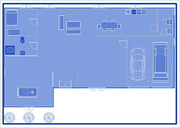
# In Hover the mouse over the design and left-click once a blue box surrounds the design. This will highlight every element in the design (Figure 1). | |||
#: [[Image:Architectural_plan_Highlight.png|400px|thumb|center| Figure 1:Highlighting elements in the Architectural plan]] | |||
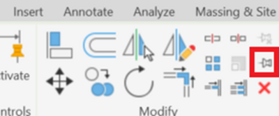
# Select the pin icon under the Modify tab (Figure 2). This prevents the linked file from being moved. | |||
# | #: [[Image:Modify_Tab.png|400px|thumb|center| Figure 2: Pin Icon]] | ||
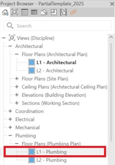
# Open the L1 - Plumbing floor plan by going to the project browser and expanding the '''Plumbing''' drop down (Figure 3). | |||
#: [[Image:Plumbing_Dropdown.jpg|400px|thumb|center| Figure 3: Plumbing Plan in Project Browser]] | |||
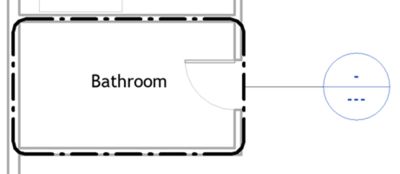
# | # Go to the '''View''' tab, select Callout. Click and drag over a large area of space containing the bathroom on the first floor (Figure 4). | ||
# Select the pin icon under the | #: [[Image:Bathroom_Callout.png|400px|thumb|center| Figure 4: Callout of the Bathroom]] | ||
# | # Go into the callout view by double-clicking on the generated circle. | ||
# | #: Select '''Plumbing Fixtures''' under the '''Systems''' tab. Under the '''Mode''' tab, select '''Load Family'''. Place a sink, toilet, and shower into the bathroom using the file paths provided in Table 1 below. | ||
# | |||
# Go to the | |||
# | |||
# | |||
# | |||
:: {| class="wikitable" | :: {| class="wikitable" | ||
|+ Table 1: File Paths for Required Plumbing Components | |+ Table 1: File Paths for Required Plumbing Components | ||
| Line 86: | Line 80: | ||
|- | |- | ||
| <center>Sink</center> | | <center>Sink</center> | ||
| | | English Imperial → Plumbing → MEP → Fixtures → Sinks → Sink - Work | ||
|- | |- | ||
| <center>Toilet</center> | | <center>Toilet</center> | ||
| | | English Imperial → Plumbing → MEP → Fixtures → Water Closets → Water Closet - Flush Tank | ||
|- | |- | ||
| <center>Shower</center> | | <center>Shower</center> | ||
| | | English Imperial → Plumbing → MEP → Fixtures → Shower → Shower Stall - Rectangular | ||
|- | |- | ||
|} | |} | ||
<ol start=" | <ol start="7"> | ||
<li> | <li> Make sure the fixtures are aligned to the wall and placed in the correct orientation. Use the spacebar to rotate the fixtures if necessary.</li> | ||
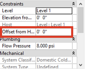
# Note | # Note: make sure that the sink is offset 3 ft off the ground in the '''Properties''' sidebar (Figure 5). | ||
<li> Three piping systems can be created: a hot water system, a cold water system, and a sanitary system. In this workshop, only the cold water system will be used. To add pipes, click on a fixture and select the | [[Image:Lab_PropertiesSidebar.png|300px|thumb|center| Figure 5: Properties Sidebar]] | ||
<li> Three piping systems can be created: a hot water system, a cold water system, and a sanitary system. In this workshop, only the cold water system will be used. To add pipes, click on a fixture and select the '''Create Pipe''' icon (Figure 6). Choose the cold water icon and not the sanitary icon.</li> | |||
<li>The pipes can be routed in any direction by left-clicking and creating joints. Click and drag the cold water pipe around the bathroom (Figure | [[Image:Create_Pipe_Icon.png|400px|thumb|center| Figure 6: Create Pipe Icon]] | ||
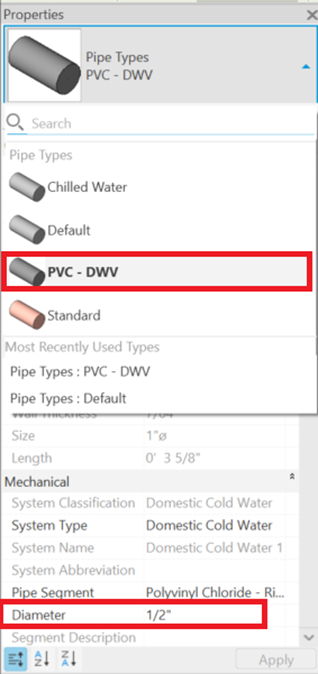
<li>In the properties section, ensure that the pipe type selected is PVC - DWV and set the diameter to ½” (Figure 7).</li> | |||
<li> Multiple fixtures can be added to the same pipeline. Select the fixture and select | [[Image:Pipe_Properties.png|400px|thumb|center| Figure 7: Pipe Properties]] | ||
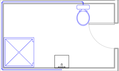
<li>The pipes can be routed in any direction by left-clicking and creating joints. Click and drag the cold water pipe around the bathroom (Figure 8).</li> | |||
[[Image:Cold_Water_Pipe.png|400px|thumb|center| Figure 8: Cold Water Pipe]] | |||
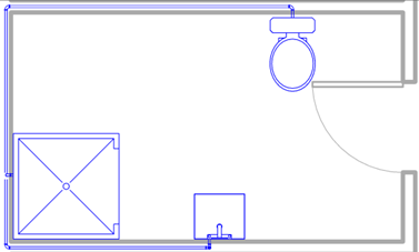
<li>Multiple fixtures can be added to the same pipeline. Select the fixture and select '''Connect Into''' under the '''Modify''' tab. Click Connector 1: Domestic Cold Water and select '''OK'''. Select the cold water pipe created in Step 12. Complete this step for the shower and the sink. The final plumbing plan for the cold water system should resemble the one in Figure 9. For the Housing in Revit SLDP, the hot water system and the sanitary system must be completed. For this workshop, move on to the electrical plan.</li> </ol> | |||
[[Image:Completed_Cold_Water_System.png|400px|thumb|center| Figure 9: Completed Cold Water System]] | |||
== Electrical Plan == | == Electrical Plan == | ||
In this part, an electrical plan will be created for the first floor of the home. Understanding the implementation of an electrical plan will be important for the completion of Benchmark B for the Housing in Revit (HIR) SLDP. | In this part, an electrical plan will be created for the first floor of the home. Understanding the implementation of an electrical plan will be important for the completion of Benchmark B for the Housing in Revit (HIR) SLDP. | ||
# Add a panelboard by accessing the ‘’’Level 1 Floor Plan’’’ of the file by clicking on the ‘’’L1 - Power’’’ option under the ‘’’Power’’’ listing of the ‘’’Project Browser’’’ (Figure 10). | |||
#: [[Image:Power Plan.png|400px|thumb|center| Figure 10: Level One Floor Power Plan]] | |||
# Select ‘’’Electrical Equipment’’’ under the ‘’’Systems’’’ tab. A panel board will be added through the ‘’’Load Family’’’ option. The ‘’’File Path’’’ to the panel board is shown in Table 2. | |||
# Add a panelboard | |||
# | |||
# Select | |||
:: {| class="wikitable" | :: {| class="wikitable" | ||
|+ Table 2: File Path for the | |+ Table 2: File Path for the Panel board | ||
|- | |- | ||
! <b>Components</b> | ! <b>Components</b> | ||
| Line 124: | Line 116: | ||
|- | |- | ||
| <center>Panelboard</center> | | <center>Panelboard</center> | ||
| Electrical → MEP → Electric Power → Distribution → Lighting and Appliance | | Electrical → MEP → Electric Power → Distribution → Lighting and Appliance Panel board - 208V MCB - Surface | ||
|- | |- | ||
|} | |} | ||
<ol start=" | |||
<li>Select the | <ol start="3"> | ||
<li> Place the selected panel board on a wall. Sometimes Autodesk Revit will not recognize it as a panel board. If this occurs, insert the panel board using the ‘’’Add Component’’’ tool. </li> | |||
<li>A branch panel schedule will appear. Click on the area to the right of | <li> Press the Esc key to deselect the panel board. Select the panel board again and it should highlight in blue. Select the dropdown arrow near the '''Create Panel Schedule''' option under the '''Modify''' tab in the project ribbon. Select Use '''Default Template''' (Figure 11). | ||
[[Image:Create Panel Schedule.png|800px|thumb|center|Figure 11: Creating Panel Schedule]] </li> | |||
<li> Return to the electrical plan of the first floor. Under the | <li> A branch panel schedule will appear. Click on the area to the right of '''Branch Panel''' and rename the schedule (Figure 12). Usually, the schedule is named after the floor the panel is located on. | ||
[[Image:Rename Schedule.png|800px|thumb|center| Figure 12: Renaming the Schedule]] </li> | |||
<li>Add switches. Select the | <li> Return to the electrical plan of the first floor. Under the '''Systems tab''', under '''Electrical''', select the '''Device''' option. In the dropdown menu, select the '''Electrical Fixture''' option. Select '''Duplex Receptacle''' under the '''Properties''' window and place the outlets along the interiors of the walls throughout the first floor of the house (Figure 13). Add at least one outlet in every room, and use the standard model unless the outlets are placed near a water source, such as a sink. In that case, use the GCFI model.</li> | ||
<li>Add ceiling lights. Open the ceiling plan of the first floor by selecting | [[Image:Sample Outlets.png|800px|thumb|center|Figure 13: Sample Outlets]] | ||
<li> Add switches. Select the '''Lighting''' option on the dropdown menu in the '''Device''' option on the '''Systems''' tab. In the '''Properties''' window, select '''Lighting Switches Circuit Breaker''' (Figure 14).</li> | |||
<li>Select | [[Image:Circuit Breaker.png|800px|thumb|center|Figure 14: Circuit Breaker]] | ||
<li> Place them next to the door so that they are within arm’s reach once the door is opened (if possible, not on the hinge side).</li> | |||
<li> Add ceiling lights. Open the ceiling plan of the first floor by selecting '''Ceiling Plans (Electrical Ceiling Plan)''' under the '''Project Browser''' (Figure 15).</li> | |||
[[Image:Electrical Ceiling Plan.png|800px|thumb|center|Figure 15: Electrical Ceiling Plans]] | |||
<li> Select '''Lighting Fixture''' under the '''Systems''' tab and '''Electrical''' subtab. Load the desired lights in through the '''Load Family''' option. The file path of the ceiling lights is shown in Table 3. Select '''Place on Face''' under the '''Modify''' tab and attach the lights to the corresponding area from the architectural plan.</li> </ol> | |||
:: {| class="wikitable" | :: {| class="wikitable" | ||
|+ Table 3: File Path for the Ceiling Lights | |+ Table 3: File Path for the Ceiling Lights | ||
| Line 148: | Line 145: | ||
|- | |- | ||
|} | |} | ||
<li>Create a circuit for the lights and a circuit for the power outlets. To generate the circuit for the lights, select any | |||
<ol start="11"> | |||
<li> Click on the | <li> Create a circuit for the lights and a circuit for the power outlets. To generate the circuit for the lights, select any '''switch''' and select Power under the '''Modify''' tab (Figure 16). In the '''Specify Circuit Information''' window that appears, select 120 V.</li> | ||
[[Image:Create Circuit.png|800px|thumb|center|Figure 16: Creating Electrical Circuit]] | |||
<li>Select | <li> Click on the '''Panel''' dropdown menu and select the panel board for the first floor (Figure 17).</li> | ||
<li>Hover over any components of the electrical circuit and click | [[Image:Panel Designation.png|600px|thumb|center|Figure 17: Panel Designation]] | ||
<li> Select '''Edit Circuit''' under the '''Modify''' tab. Select the ceiling lights that are connected to the circuit. Select the green check mark to complete the circuit. Repeat this step for all the switches and their corresponding lights.</li> | |||
<li>Under the | <li> Hover over any components of the electrical circuit and click '''Tab''' on the keyboard. A dashed representation of the circuit will temporarily be displayed. Click on the component that was hovered over to create a permanent display (Figure 18).</li> | ||
[[Image:Circuit Display.png|800px|thumb|center|Figure 18: Circuit Display]] | |||
<li> Go back to the | <li> Under the Modify tab, select either Arc Wire or Chamfered Wire. Solid wires will appear to connect all the circuit components and the panel board (Figure 19).</li> | ||
<li> Repeat steps | [[Image:Add Wires.png|800px|thumb|center|Figure 19: Adding Wire to the Circuit]] | ||
<li> The electrical plan is now completed. Only the electrical plan for the first floor will be made for this workshop. Move on to the creation and connection of multiple floors. </li> | <li> Go back to the '''Panel Schedule''' view under the '''Project Browser.''' A new circuit should appear. Rename the '''Circuit Description''' with an appropriate title, such as organization by the type of room.</li> | ||
</ol> | <li> Repeat steps 11-16 for the outlets instead of the lights and switches. Each outlet should be connected to the panel board.</li> | ||
<li> The electrical plan is now completed. Only the electrical plan for the first floor will be made for this workshop. Move on to the creation and connection of multiple floors.</li> </ol> | |||
== Complete the Architectural Plan == | == Complete the Architectural Plan == | ||
In this part, a third floor will be added to the architectural plan. All three floors will then be connected by stairs. A roof will be added to finish the design of the house. | In this part, a third floor will be added to the architectural plan. All three floors will then be connected by stairs. A roof will be added to finish the design of the house. | ||
# Return to the architectural floor plan. | |||
# | # Add a third floor. To add multiple floors, use the same procedure. Select one of the Elevations views under the Project Browser window (Figure 20). | ||
# Add a third floor. To add multiple floors, use the same procedure. Select one of the | #: [[Image:Lab_RevitElevations.jpg|400px|thumb|center| Figure 22: Elevations View]] | ||
# | # Select the <b>Datum Level</b> tool in the project ribbon. (Figure 21). | ||
# Select the <b>Datum</b> | #: [[Image:Lab_RevitDatum.jpg|400px|thumb|center| Figure 23: Datum Level Tool]] | ||
# | # Left-click and draw a line in the project space 10 feet above the previous floor to create the elevation. The project browser should be updated with the new elevation views (Figure 22). | ||
# Left-click and draw a line in the project space 10 feet above the previous floor to create the elevation. The project browser should be updated with the new elevation views | #: [[Image:Lab_Elevation.png|400px|thumb|center| Figure 24: Creating New Elevation]] | ||
# | # To extend the walls to the new floor, select the '''Level 1 Floor Plan''' in the '''Project Browser''' window. Highlight all the walls by holding down Ctrl and left clicking the walls. In the '''Properties''' window, change the '''Top Offset''' to the height of the top floor. In this workshop, the offset should be 20 ft (Figure 23). | ||
# To extend the walls to the new floor, select the | |||
## To verify any component in the 3D View, hide elements, such as walls, ceilings, and floors, by right-clicking on the elements and selecting <b>Hide in View</b>. They can be unhidden by selecting the lightbulb icon in the bottom to reveal hidden elements. Red outlines of the hidden elements will be displayed. Selecting <b>Unhide in View</b> once selected will unhide the elements. | ## To verify any component in the 3D View, hide elements, such as walls, ceilings, and floors, by right-clicking on the elements and selecting <b>Hide in View</b>. They can be unhidden by selecting the lightbulb icon in the bottom to reveal hidden elements. Red outlines of the hidden elements will be displayed. Selecting <b>Unhide in View</b> once selected will unhide the elements. | ||
# | #: [[Image:Lab_RevitOffset.jpg|400px|thumb|center| Figure 25: Changing Top Offset of the Walls]] | ||
# Create a ceiling for the second floor. Select the <b>Level 2 Ceiling Plan</b> under the <b>Project Browser</b> window. Select the <b>Ceiling</b> tool in the <b>Architecture</b> tab. Select the <b>Automatic Ceiling</b> option under the <b>Modify</b> tab. Select the area within the floor to create the ceiling (Figure 24). | # Create a ceiling for the second floor. Select the <b>Level 2 Ceiling Plan</b> under the <b>Project Browser</b> window. Select the <b>Ceiling</b> tool in the <b>Architecture</b> tab. Select the <b>Automatic Ceiling</b> option under the <b>Modify</b> tab. Select the area within the floor to create the ceiling (Figure 24). | ||
# | #: [[Image:Lab_RevitCeilingFinish.jpg|600px|thumb|center| Figure 24: Automatic Ceiling]] | ||
# Create a floor for the third floor. Select the | # Create a floor for the third floor. Select the '''Level 3 Floor Plan''' under the '''Project Browser''' window. Then select '''Floor: Architectural''' in the Architecture tab, and use the line tools in the Draw tab to outline the inner edge of the outer walls (Figure 25). Then select the '''green check mark.''' | ||
# | #: [[Image:Lab_RevitFloor.jpg|600px|thumb|center| Figure 25: Adding the Floor]] | ||
# Repeat step | # Repeat step 6 for the ceiling on the third floor. | ||
# Add a shaft and stairs to connect the three floors. Select the <b>Level 1 Floor Plan</b> in the <b>Project Browser</b> window. Select the <b>Shaft</b> option in the <b>Architecture</b> tab (Figure 26). | # Add a shaft and stairs to connect the three floors. Select the <b>Level 1 Floor Plan</b> in the <b>Project Browser</b> window. Select the <b>Shaft</b> option in the <b>Architecture</b> tab (Figure 26). | ||
# | #: [[Image:Lab_RevitShaft.jpg|400px|thumb|center| Figure 26: Shaft Option]] | ||
# Draw the area of the shaft in an open area. Make the shaft larger than necessary. The size of the shaft can be adjusted after the staircase is placed. The shaft should be placed carefully since it can run through different elements of other floors. | # Draw the area of the shaft in an open area. Make the shaft larger than necessary. The size of the shaft can be adjusted after the staircase is placed. The shaft should be placed carefully since it can run through different elements of other floors. | ||
# Select the <b>Stair</b> option under the <b>Architecture</b> tab. Click and drag the stairs along the shaft to create the stairs. If an error message appears, that means that the stairs are not long enough to extend to the next floor. Extend the stairs and adjust the shaft so that they fit (Figure 27). Alternatively, the <b>Desired Number of Risers</b> under the <b>Properties</b> window and the <b>Actual Run Width</b> under the <b>Project</b> ribbon can be used to adjust the staircase to fit the shaft. | # Select the <b>Stair</b> option under the <b>Architecture</b> tab. Click and drag the stairs along the shaft to create the stairs. If an error message appears, that means that the stairs are not long enough to extend to the next floor. Extend the stairs and adjust the shaft so that they fit (Figure 27). Alternatively, the <b>Desired Number of Risers</b> under the <b>Properties</b> window and the <b>Actual Run Width</b> under the <b>Project</b> ribbon can be used to adjust the staircase to fit the shaft. | ||
## For multiple levels, select <b>Connect Levels</b> under the <b>Modify</b> tab when editing the stairs. In the window that appears, select the levels that the stairs should connect to. Click the green check mark to finish editing. | ## For multiple levels, select <b>Connect Levels</b> under the <b>Modify</b> tab when editing the stairs. In the window that appears, select the levels that the stairs should connect to. Click the green check mark to finish editing. | ||
# | #: [[Image:Lab_RevitStairs.jpg|400px|thumb|center| Figure 27: Creating Stairs]] | ||
# Select the shaft. In the <b>Properties</b> window, change the base offset of the shaft to 0 ft so that there is not a hole in the floor. The stairs are now completed. | # Select the shaft. In the <b>Properties</b> window, change the base offset of the shaft to 0 ft so that there is not a hole in the floor. The stairs are now completed. | ||
# Create a roof. Follow steps 3 - 4 to create a <b>Level 4</b>. Select the <b>Level 3 Floor Plan</b> in the <b>Project Browser</b> window. Select the <b>Roof</b> option in the <b>Architecture</b> tab. In the <b>Properties</b> window, change the <b>Base Level</b> to <b>Level 4</b>. Select the outer layers of the walls, then select the green check mark to complete the roof (Figure 28). | # Create a roof. Follow steps 3 - 4 to create a <b>Level 4</b>. Select the <b>Level 3 Floor Plan</b> in the <b>Project Browser</b> window. Select the <b>Roof</b> option in the <b>Architecture</b> tab. In the <b>Properties</b> window, change the <b>Base Level</b> to <b>Level 4</b>. Select the outer layers of the walls, then select the green check mark to complete the roof (Figure 28). | ||
# | #: [[Image:Lab_RevitRoof.jpg|400px|thumb|center| Figure 28: Completed Roof]] | ||
== Designing the Third Floor == | == Designing the Third Floor == | ||
| Line 203: | Line 200: | ||
= Assignment = | = Assignment = | ||
This workshop provided introductory skills required to complete the HIR SLDP. Benchmark A, the first SLDP checkpoint, will be due at the end of Model Shop Session 2. Please refer to the SLDP page for information about the assignments required for Benchmark A. | |||
= References = | = References = | ||
Autodesk. “Autodesk Revit Overview.” Autodesk, | Autodesk. “Autodesk Revit Overview.” Autodesk, 2022. Retrieved 6 January 2022. http://www.imaginit.com/portals/4/documents/autodesk-revit2018-brochure_evergreen_v3.pdf | ||
U.S. Green Building Council. “LEED v4 for Building Design and Construction.” USGBC, 2019. Retrieved 8 August 2021. https://www.usgbc.org/sites/default/files/LEED%20v4%20BDC_07.25.19_current.pdf. | U.S. Green Building Council. “LEED v4 for Building Design and Construction.” USGBC, 2019. Retrieved 8 August 2021. https://www.usgbc.org/sites/default/files/LEED%20v4%20BDC_07.25.19_current.pdf. | ||
| Line 221: | Line 214: | ||
# Starting on the lower floor, change the Sloped Piping option to “Slope Up”. Change the middle elevation to the desired elevation. To connect pipes of consecutive floors, change the middle elevation to 10 ft. | # Starting on the lower floor, change the Sloped Piping option to “Slope Up”. Change the middle elevation to the desired elevation. To connect pipes of consecutive floors, change the middle elevation to 10 ft. | ||
# Check if the piping connection was successful by going to the <b>3D View</b>. A circle icon will display between the pipes if the connection was successful. | # Check if the piping connection was successful by going to the <b>3D View</b>. A circle icon will display between the pipes if the connection was successful. | ||
== Walkthrough Video == | |||
A walkthrough is a method of rendering a Revit model to provide an interactive look at the project. Use the following steps to create a walkthrough video. | |||
# Define the camera path for the walkthrough. | |||
##To do this, select the '''3D View''' in the access toolbar. Click the '''3D view''' drop-down menu -> '''Walkthrough''' (Figure 17). Click points in the view to establish the path that the camera will follow. Change the offset in the '''Options''' bar to adjust the height of the camera.[[File:Walkthrough_in_View_Tab.PNG|600px|thumb|center|Figure 17: Walkthrough in View Tab]] | |||
##After defining the path, click <b>Finish Walkthrough</b>. A walkthrough branch will be added to the '''Project Browser''' now (Figure 18). Review the walkthrough video.[[File:Walkthrough_in_Project_Browser.PNG|600px|thumb|center|Figure 18: Walkthrough in Project Browser]] | |||
#Edit the walkthrough video. | |||
##When previewing the walkthrough video, the view is static and displays one frame only. To adjust what is visible in the camera, open an '''Elevations''' view (North/South/East/West) in the '''Project Browser'''. Then select the '''Tiles''' tool to tile these views with the walkthrough video. | |||
## Select the crop region of the walkthrough and click '''Edit Walkthrough'''. Set the frame control on the '''Option''' bar to 1 to bring the camera back to the beginning position of the walkthrough. Activate the '''Site Plan''' view and set the '''Controls''' to '''Active Camera''' on the '''Options''' bar. Use the grip controls on the camera to adjust the target position and the view depth of the walkthrough camera. The walkthrough video will be updated as the camera is adjusted | |||
##Click the '''Edit Walkthrough''' tab and use the playback controls to check and review the walkthrough video as it is made. | |||
{{Laboratory Experiments}} | |||
Revision as of 16:50, 25 September 2024
Objective
The objective of this workshop is to analyze and complete an incomplete house plan with an electrical plan, a plumbing plan, an extra story (floor), a roof, and additional utilities using Autodesk Revit.
Overview
Revit
Autodesk Revit is a Building Information Modeling (BIM) software used by architects, engineers, and contractors to plan, design, construct, and manage building and infrastructure designs. For architects, Revit is used to create floor plans, elevations, and 3D views in addition to rendering and animating the building design. For structural engineers, Revit is used to analyze and evaluate how well a building conforms to building and safety regulations. For mechanical, electrical, and plumbing (MEP) engineers, Revit allows coordination with architects and other engineers to design systems with all the architectural and structural components. For construction professionals, Revit is used to plan and understand construction methods, materials, and schedules.
Plumbing & Electrical Plans
In addition to other technical drawings, architects, engineers, and contractors require plumbing and electrical plans to accurately construct buildings. Plumbing plans show various plumbing fixtures, such as sinks, toilets, and showers, and the pipes connecting these fixtures to water sources and disposal systems. There are three main types of water systems: hot water, cold water, and sanitary water. Hot and cold water systems introduce filtered, ready-to-use water into the plumbing system while sanitary systems remove wastewater from the system and route this water to treatment facilities. Plumbing plans ensure that each component receives the right type of water and has adequate disposal of wastewater.
Electrical plans show the electrical components within a building. These schematics include the electrical circuits within the system. Each electrical circuit is routed to a centralized panel board that houses circuit breakers and fuses, one for each electrical circuit. Electrical plans also show electrical outlets that have two main types: default and ground fault circuit interrupters (GFCI). GFCI outlets are mainly used near water sources as they help prevent water damage to circuits that can cause fatal accidents where current can be inadvertently directed away from the outlet and cause shock. Electrical plans direct the wiring of outlets and other appliances.
LEED Accreditation
Leadership in Energy and Environmental Design (LEED) is an internationally used green building certification program developed by the U.S. Green Building Council. To receive LEED certification, building projects must satisfy prerequisites and earn points to achieve different levels of certification. The different categories for the LEED checklist correspond to principles of design, construction, and maintenance. The eight LEED categories with brief descriptions are:
- Location and Transportation
- Diverse land use
- Disability access
- Bicycle and EV facilities
- Reduced parking footprint
- Sustainable Sites
- Open space
- Rainwater management
- Heat island reduction
- Light pollution reduction
- Water Efficiency
- Water quality management
- Water use reduction
- Water heating and cooling
- Advanced water metering
- Energy and Atmosphere
- Optimize energy performance
- Advanced energy metering
- Demand response
- Renewable energy production
- Materials and Resources
- Waste reduction
- Avoid mercury containing materials and devices
- Using reusable materials for which life-cycle information is known
- Indoor Environmental Quality
- Air quality management
- Interior lighting/daylight
- Thermal comfort
- Acoustic performance
- Innovation
- Connected building
- Intelligent inventory
- Security and safety
- Sustainability not covered in other topics
- Regional Priority
- Addressing region-specific environmental, social equity, and public health priorities
Third-Party Revit Components
While Revit has a wide range of components, additional components can be downloaded from third-party websites and imported into existing Revit files. Common third-party websites include BIMObject, BIMSmith, and RevitCity. These websites are continuously updated with new components. Making an account with one of these sites will be extremely beneficial in the completion of both your project and this workshop.
Materials and Equipment
- Autodesk Revit 2025 or newer
Procedure
In this workshop, an electrical plan, a plumbing plan, designing and connecting multiple floors, and designing a roof will be completed. An incomplete two-floor house plan is provided to explore these skills. Download the incomplete two-floor house plan RVT file here. To avoid compatibility issues, use Autodesk Revit 2025 or a newer version. The file that is attached above is a .zip file. To extract the files you must download it, click on the folder once, then at the top ribbon click “Extract”. From there you will be able to open the relevant files to complete this workshop.
Plumbing Plan
In this part, a plumbing plan will be created for one bathroom on the first floor. Understanding the implementation of a plumbing plan will be important for the completion of Benchmark B for the Housing in Revit (HIR) semester-long design project (SLDP).
- Open the file above.
- In Hover the mouse over the design and left-click once a blue box surrounds the design. This will highlight every element in the design (Figure 1).
- Select the pin icon under the Modify tab (Figure 2). This prevents the linked file from being moved.
- Open the L1 - Plumbing floor plan by going to the project browser and expanding the Plumbing drop down (Figure 3).
- Go to the View tab, select Callout. Click and drag over a large area of space containing the bathroom on the first floor (Figure 4).
- Go into the callout view by double-clicking on the generated circle.
- Select Plumbing Fixtures under the Systems tab. Under the Mode tab, select Load Family. Place a sink, toilet, and shower into the bathroom using the file paths provided in Table 1 below.
Table 1: File Paths for Required Plumbing Components Components File Paths Sink English Imperial → Plumbing → MEP → Fixtures → Sinks → Sink - Work Toilet English Imperial → Plumbing → MEP → Fixtures → Water Closets → Water Closet - Flush Tank Shower English Imperial → Plumbing → MEP → Fixtures → Shower → Shower Stall - Rectangular
- Make sure the fixtures are aligned to the wall and placed in the correct orientation. Use the spacebar to rotate the fixtures if necessary.
- Note: make sure that the sink is offset 3 ft off the ground in the Properties sidebar (Figure 5).
- Three piping systems can be created: a hot water system, a cold water system, and a sanitary system. In this workshop, only the cold water system will be used. To add pipes, click on a fixture and select the Create Pipe icon (Figure 6). Choose the cold water icon and not the sanitary icon.
- In the properties section, ensure that the pipe type selected is PVC - DWV and set the diameter to ½” (Figure 7).
- The pipes can be routed in any direction by left-clicking and creating joints. Click and drag the cold water pipe around the bathroom (Figure 8).
- Multiple fixtures can be added to the same pipeline. Select the fixture and select Connect Into under the Modify tab. Click Connector 1: Domestic Cold Water and select OK. Select the cold water pipe created in Step 12. Complete this step for the shower and the sink. The final plumbing plan for the cold water system should resemble the one in Figure 9. For the Housing in Revit SLDP, the hot water system and the sanitary system must be completed. For this workshop, move on to the electrical plan.
Electrical Plan
In this part, an electrical plan will be created for the first floor of the home. Understanding the implementation of an electrical plan will be important for the completion of Benchmark B for the Housing in Revit (HIR) SLDP.
- Add a panelboard by accessing the ‘’’Level 1 Floor Plan’’’ of the file by clicking on the ‘’’L1 - Power’’’ option under the ‘’’Power’’’ listing of the ‘’’Project Browser’’’ (Figure 10).
- Select ‘’’Electrical Equipment’’’ under the ‘’’Systems’’’ tab. A panel board will be added through the ‘’’Load Family’’’ option. The ‘’’File Path’’’ to the panel board is shown in Table 2.
Table 2: File Path for the Panel board Components File Paths Panelboard Electrical → MEP → Electric Power → Distribution → Lighting and Appliance Panel board - 208V MCB - Surface
- Place the selected panel board on a wall. Sometimes Autodesk Revit will not recognize it as a panel board. If this occurs, insert the panel board using the ‘’’Add Component’’’ tool.
- Press the Esc key to deselect the panel board. Select the panel board again and it should highlight in blue. Select the dropdown arrow near the Create Panel Schedule option under the Modify tab in the project ribbon. Select Use Default Template (Figure 11).
- A branch panel schedule will appear. Click on the area to the right of Branch Panel and rename the schedule (Figure 12). Usually, the schedule is named after the floor the panel is located on.
- Return to the electrical plan of the first floor. Under the Systems tab, under Electrical, select the Device option. In the dropdown menu, select the Electrical Fixture option. Select Duplex Receptacle under the Properties window and place the outlets along the interiors of the walls throughout the first floor of the house (Figure 13). Add at least one outlet in every room, and use the standard model unless the outlets are placed near a water source, such as a sink. In that case, use the GCFI model.
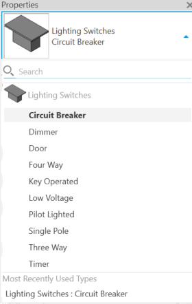
- Add switches. Select the Lighting option on the dropdown menu in the Device option on the Systems tab. In the Properties window, select Lighting Switches Circuit Breaker (Figure 14).
- Place them next to the door so that they are within arm’s reach once the door is opened (if possible, not on the hinge side).
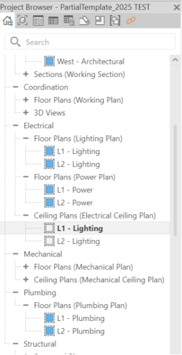
- Add ceiling lights. Open the ceiling plan of the first floor by selecting Ceiling Plans (Electrical Ceiling Plan) under the Project Browser (Figure 15).
- Select Lighting Fixture under the Systems tab and Electrical subtab. Load the desired lights in through the Load Family option. The file path of the ceiling lights is shown in Table 3. Select Place on Face under the Modify tab and attach the lights to the corresponding area from the architectural plan.
Table 3: File Path for the Ceiling Lights Components File Paths Ceiling Light Lighting → MEP → Internal → Ceiling Light - Flat Round
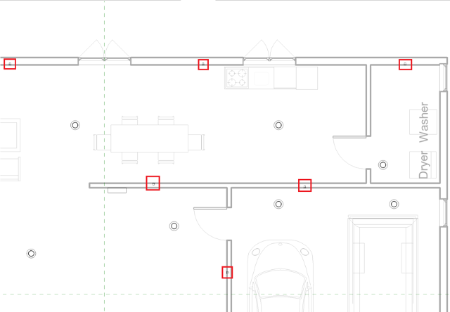
- Create a circuit for the lights and a circuit for the power outlets. To generate the circuit for the lights, select any switch and select Power under the Modify tab (Figure 16). In the Specify Circuit Information window that appears, select 120 V.
- Click on the Panel dropdown menu and select the panel board for the first floor (Figure 17).
- Select Edit Circuit under the Modify tab. Select the ceiling lights that are connected to the circuit. Select the green check mark to complete the circuit. Repeat this step for all the switches and their corresponding lights.
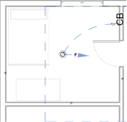
- Hover over any components of the electrical circuit and click Tab on the keyboard. A dashed representation of the circuit will temporarily be displayed. Click on the component that was hovered over to create a permanent display (Figure 18).
- Under the Modify tab, select either Arc Wire or Chamfered Wire. Solid wires will appear to connect all the circuit components and the panel board (Figure 19).
- Go back to the Panel Schedule view under the Project Browser. A new circuit should appear. Rename the Circuit Description with an appropriate title, such as organization by the type of room.
- Repeat steps 11-16 for the outlets instead of the lights and switches. Each outlet should be connected to the panel board.
- The electrical plan is now completed. Only the electrical plan for the first floor will be made for this workshop. Move on to the creation and connection of multiple floors.
Complete the Architectural Plan
In this part, a third floor will be added to the architectural plan. All three floors will then be connected by stairs. A roof will be added to finish the design of the house.
- Return to the architectural floor plan.
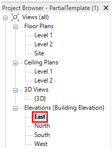
- Add a third floor. To add multiple floors, use the same procedure. Select one of the Elevations views under the Project Browser window (Figure 20).
- Select the Datum Level tool in the project ribbon. (Figure 21).
- Left-click and draw a line in the project space 10 feet above the previous floor to create the elevation. The project browser should be updated with the new elevation views (Figure 22).
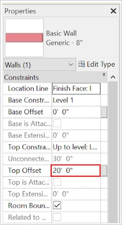
- To extend the walls to the new floor, select the Level 1 Floor Plan in the Project Browser window. Highlight all the walls by holding down Ctrl and left clicking the walls. In the Properties window, change the Top Offset to the height of the top floor. In this workshop, the offset should be 20 ft (Figure 23).
- To verify any component in the 3D View, hide elements, such as walls, ceilings, and floors, by right-clicking on the elements and selecting Hide in View. They can be unhidden by selecting the lightbulb icon in the bottom to reveal hidden elements. Red outlines of the hidden elements will be displayed. Selecting Unhide in View once selected will unhide the elements.
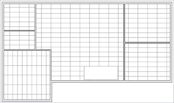
- Create a ceiling for the second floor. Select the Level 2 Ceiling Plan under the Project Browser window. Select the Ceiling tool in the Architecture tab. Select the Automatic Ceiling option under the Modify tab. Select the area within the floor to create the ceiling (Figure 24).
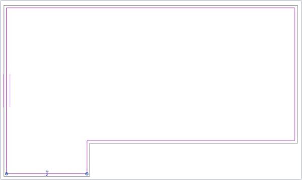
- Create a floor for the third floor. Select the Level 3 Floor Plan under the Project Browser window. Then select Floor: Architectural in the Architecture tab, and use the line tools in the Draw tab to outline the inner edge of the outer walls (Figure 25). Then select the green check mark.
- Repeat step 6 for the ceiling on the third floor.
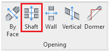
- Add a shaft and stairs to connect the three floors. Select the Level 1 Floor Plan in the Project Browser window. Select the Shaft option in the Architecture tab (Figure 26).
- Draw the area of the shaft in an open area. Make the shaft larger than necessary. The size of the shaft can be adjusted after the staircase is placed. The shaft should be placed carefully since it can run through different elements of other floors.
- Select the Stair option under the Architecture tab. Click and drag the stairs along the shaft to create the stairs. If an error message appears, that means that the stairs are not long enough to extend to the next floor. Extend the stairs and adjust the shaft so that they fit (Figure 27). Alternatively, the Desired Number of Risers under the Properties window and the Actual Run Width under the Project ribbon can be used to adjust the staircase to fit the shaft.
- For multiple levels, select Connect Levels under the Modify tab when editing the stairs. In the window that appears, select the levels that the stairs should connect to. Click the green check mark to finish editing.
- Select the shaft. In the Properties window, change the base offset of the shaft to 0 ft so that there is not a hole in the floor. The stairs are now completed.
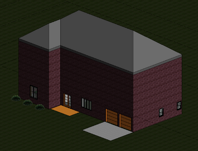
- Create a roof. Follow steps 3 - 4 to create a Level 4. Select the Level 3 Floor Plan in the Project Browser window. Select the Roof option in the Architecture tab. In the Properties window, change the Base Level to Level 4. Select the outer layers of the walls, then select the green check mark to complete the roof (Figure 28).
Designing the Third Floor
Only complete this part of the workshop if there is extra time in the workshop session. Otherwise, begin working on the Housing in Revit SLDP.
Design the interior floor plan of the third floor of the building. Make sure to have at least one bathroom and one bedroom. Windows and lights should be added as needed. Try to use one imported component from a third-party website. To import a component, follow the procedure.
- Go to revitcity.com or market.bimsmith.com
- Create an account.
- Search for the desired components.
- Download the component.
- Place the downloaded component into Autodesk Revit through the Load Family option under the Insert tab.
Assignment
This workshop provided introductory skills required to complete the HIR SLDP. Benchmark A, the first SLDP checkpoint, will be due at the end of Model Shop Session 2. Please refer to the SLDP page for information about the assignments required for Benchmark A.
References
Autodesk. “Autodesk Revit Overview.” Autodesk, 2022. Retrieved 6 January 2022. http://www.imaginit.com/portals/4/documents/autodesk-revit2018-brochure_evergreen_v3.pdf
U.S. Green Building Council. “LEED v4 for Building Design and Construction.” USGBC, 2019. Retrieved 8 August 2021. https://www.usgbc.org/sites/default/files/LEED%20v4%20BDC_07.25.19_current.pdf.
Appendix
Multi-Floor Plumbing
- To connect multi-level plumbing plans, edit the middle elevation to match the elevation of the pipe on the higher level.
- Modify the pipes in any higher levels so that there is a pipe running along the floor of that level by changing the middle elevation to 0 ft.
- Starting on the lower floor, change the Sloped Piping option to “Slope Up”. Change the middle elevation to the desired elevation. To connect pipes of consecutive floors, change the middle elevation to 10 ft.
- Check if the piping connection was successful by going to the 3D View. A circle icon will display between the pipes if the connection was successful.
Walkthrough Video
A walkthrough is a method of rendering a Revit model to provide an interactive look at the project. Use the following steps to create a walkthrough video.
- Define the camera path for the walkthrough.
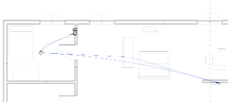
- To do this, select the 3D View in the access toolbar. Click the 3D view drop-down menu -> Walkthrough (Figure 17). Click points in the view to establish the path that the camera will follow. Change the offset in the Options bar to adjust the height of the camera.
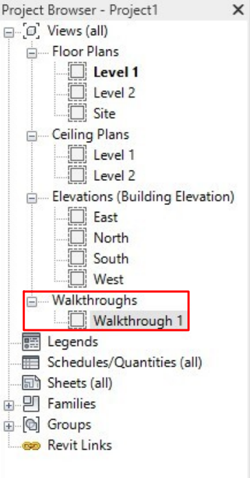
- After defining the path, click Finish Walkthrough. A walkthrough branch will be added to the Project Browser now (Figure 18). Review the walkthrough video.
- Edit the walkthrough video.
- When previewing the walkthrough video, the view is static and displays one frame only. To adjust what is visible in the camera, open an Elevations view (North/South/East/West) in the Project Browser. Then select the Tiles tool to tile these views with the walkthrough video.
- Select the crop region of the walkthrough and click Edit Walkthrough. Set the frame control on the Option bar to 1 to bring the camera back to the beginning position of the walkthrough. Activate the Site Plan view and set the Controls to Active Camera on the Options bar. Use the grip controls on the camera to adjust the target position and the view depth of the walkthrough camera. The walkthrough video will be updated as the camera is adjusted
- Click the Edit Walkthrough tab and use the playback controls to check and review the walkthrough video as it is made.
| ||||||||
