Railroad Train Guidance System (RTGS)
RFP*: Train Guidance System
* RFP is an acronym for Request For Proposal. Internationally, RFPs are called ITTs, an acronym for Invitation To Tender. Companies and governmental agencies use RFPs to solicit new business.
Introduction and Overview:
The East side of Manhattan has grown steadily since the early 1940s, when the area began to change from an industrial district into a residential neighborhood. Since the two elevated train lines over Second (1942) and Third (1956) Avenues were taken down, the area has been served by the Lexington Avenue line alone.1 Passenger loads on the 4 and 5 Express trains exceed transportation guidelines. Plans have been proposed to alleviate this congestion since the early 1930s. A plan developed in the 1960s led to the construction of several tunnel segments, but was abandoned during the city's fiscal crisis in the 1970s. Many ideas have been proposed and abandoned, due to strong opposition by various groups. The current project has a high probability of being implemented. Once completed, the project will include a two-track line along Second Avenue from 125th Street to the Financial District in Lower Manhattan. It will also include a connection from Second Avenue through the 63rd Street tunnel to existing tracks for service to West Midtown and Brooklyn. The Second Avenue Line will be a boon to those who live and work on the East Side of Manhattan, finally having an alternative to the frenzied congestion of the Lexington Avenue Subway.
The Metropolitan Transportation Authority (MTA) New York City Transit is responsible for the safe and efficient transportation of hundreds of thousands of New Yorkers each day. The vast and complex subway system is home to dozens of train lines and hundreds of stations. Currently, many capital construction projects are underway, including the East Side Access MTA Long Island Railroad Grand Central Connection, which will connect the Long Island Railroad's Main and Port Washington Lines to a new Terminal under Grand Central Station in Manhattan. Although this will help East Side access for Long Island commuters, It will put even more pressure on the 4 and 5 lines, making completion of the Second Avanue Subway line even more important.
In addition to the two tracks, there will also be places where more tracks will be necessary for connections to other lines, bypass when track work is underway, future growth, connection to maintenance facilities, etc.
The Second Avenue Line is in the planning stages. MTA New York City Transit is requesting proposals for the design of the switches and signals for this project. You are competing for a contract to design and program the logic responsible for safely guiding the trains along the Second Avenue Line. A major part of the competition is to demonstrate your capabilities by using digital logic to efficiently control a section of track specified by MTA New York City Transit. For more information, see http://www.mta.nyc.ny.us/capconstr/.
Your plan must be innovative. The winning proposal will be the one that combines solid engineering with a deep understanding of the problem and its solution. For this project, you’ll be writing a proposal cover letter. Your letter should include information on your company and its lead developers with at least one reference to a previous project.
Please refer to the EG specifications for writing the proposal cover letter. The format outlined in the Technical Communication section of the online EG manual is the one you should use.
Prerequisite
If you have not already done the EG1004 Digital Logic Lab, you will probably find the rest of this document confusing. If you have not already done this lab, stop now and read the following sections in this lab:
- 1 Overview
- 5 Sample Problem
Then come back and read this document.
Specifications:
As part of this project, you are required to use digital logic to design Boolean equations that will be used to control the track switches along the right of way. This includes creating truth tables, transforming these truth tables into simplified Boolean equations, and implementing your equations with digital logic, using LabVIEW to control the train track, allowing a locomotive to safely navigate the track from left to right, and back again.
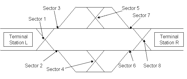
The route the train can take is controlled by track switches arranged into 8 sectors, as shown in Figure 1. Sectors 1, 4, 5, and 8 are called “X�? sectors because the combination of the four track switches make a letter “X�?, and the train can either travel straight or cross over to another track. Sectors 2, 3, 6, and 7 are called “Y�? sectors because the sector consists of a single track switch that looks like the letter “Y�?, and can choose one of two tracks to merge with one track.
Figure 1: Track Layout
Your logic design will throw the track switches to allow a train to travel from Terminal Station L to Terminal Station R, reverse direction, and travel from the Terminal Station R back to Terminal Station L. The train can leave from either side of Terminal Station L, and can arrive on either side of Terminal Station R. Similarly, on the return trip, the train can arrive on either side of Terminal Station L.
This trip can be made in the Normal Mode or the Reverse Running Mode. In Normal Mode, defined by MTA New York City Transit, only the Sectors 2, 4, and 6 tracks are used for travel from left to right. Sectors 7, 5, and 3 are used for travel from right to left. In summary, the train must “keep to the right�?, like cars on a highway. In Reverse Running Mode, defined by the Northeast Operating Rules Advisory Committee Rule 261, all the tracks can be used to travel in either direction.
For normal mode, the train leaves Terminal Station L, and crosses Sector 1, if necessary, to get to Sector 2. At Sector 2, you have a choice of using the inner or outer track. Since the optimal path between two points is a straight line, its ideal path would be the inside tracks of Sectors 2, 4, and Sector 6, crossing Sector 8, if necessary, to arrive on the proper track at Terminal Station R. For the return trip, the train would cross Sector 8, if necessary, to get to Sector 7. Its ideal path would be the inside tracks of Sectors 7, 5, and 3, crossing Sector 1, if necessary, to arrive on the proper track at Terminal Station L.
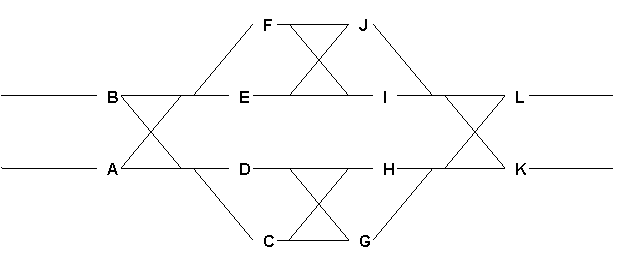
Your train will not be the only train running on the tracks. As part of the specifications, there will be 12 possible locations for other trains to be on the tracks. Your Boolean equations and LabVIEW programs must compensate for this, and allow your train to get through.
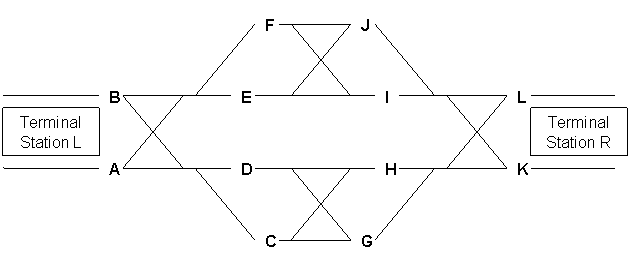
Figure 2: Possible Locations for Other Trains
Your task is to design a digital logic system that will allow the train to travel from one end of the track layout to the other, and to return to the starting point using the designated departure and arrival tracks. During testing, your TA will place railroad cars to some of the locations, A through K, shown in Figure 2, blocking paths. Your logic will then throw the train switches (as described below) to allow the locomotive to travel from Terminal Station L to Terminal Station R, where the locomotive will stop. The TA will change the railroad cars to other locations, and your logic will throw the switches for the return trip. Note that the arrival and departure tracks of the two terminals may be dictated by cars blocking at Locations A, B, K, or L. If both tracks at a terminal are available, you can use either one.
The EG staff has already done much of the work for you, providing Virtual Instruments (VIs) that will tell you which of the locations in Figure 2 are blocked, and accepting outputs from your VI as described below to actually throw the track switches. Design a LabVIEW VI which contains a digital logic circuit that accepts the following inputs:
- The status of each of the 12 locations, i.e., whether they are occupied or not. This information will come from a VI provided by the EG staff.
- A switch included in LabVIEW that indicates the direction of the train's travel, i.e., from left to right or right to left.
- A switch included in LabVIEW that indicates whether the train’s travel will be via Normal Mode or Reverse Running Mode
Your digital logic must provide the following outputs:
- If one or more paths is available, supply the digital logic outputs for the settings of the track switches for each of the eight sectors to the VI provided by the EG staff. This VI will throw the switches according to your specification, allowing the train to travel from one Terminal Station to the other.
- A red light included in LabVIEW on the Front Panel that illuminates if there is no path available.
After your VI has set the switches, your TA will drive the train from the Terminal Station L to Terminal Station R, and move the blocking cars. After your VI sets the switches for the return trip, your TA will drive the locomotive back to the Terminal Station L.
MICROSOFT PROJECT
Your team must create a time management plan using Microsoft Project (MS Project). You can learn Microsoft Project by doing the MS Project Skill Builder contained elsewhere in this manual. This plan must include all tasks related to the project. Each task must be named, assigned a duration and assigned to a specific person (or people). You must begin your work by creating an MS Project plan. Follow your project plan throughout the semester. If the team falls behind schedule, explain the reasons for the delays when you present your progress reports, list the steps being taken to get the project back on track, and create a revised MS Project plan.
For help in planning your project, review the page called How to plan the schedule and calculate costs for a project in the section called Material to help you with the project elsewhere in this manual.
There should be at least twenty tasks/subtasks and three Milestones. Milestones should be noted with the duration of "0day". Moreover, the copy picture function included in MS Project Software should be used instead of the print screen function of the computer.
COST ESTIMATE
You will need to create a cost estimate using quotes from a reputable vendor. Examples are Digikey (http://www.digikey.com), Newark Electronics/Newark In One (http://www.newark.com), and On Semiconductor (http://www.onsemi.com). You are not limited to these vendors. This cost estimate includes prices for TTL Logic Chips for the various logic gates you use in your LabVIEW VI. When doing your cost estimate, be sure to include specification sheets from the vendors for all of the chips that you may use.
Once a robot design is complete, a cost estimate must be generated that specifies the cost of all the materials and labor required for the construction of your design. Tabulate this cost information clearly in an Excel spreadsheet, using the materials cost list provided. You can get help in calculating the cost by reviewing the page called How to plan the schedule and calculate costs for a project in the section called Material to help you with the project elsewhere in this manual.
Have all the materials and parts used categorized in different groups instead of including individual parts. Make sure to include the units of each part used in a group and total them up for that individual group. Moreover, the cost of labor should be included. You can get help on the labor cost by reading the page How to plan the schedule and calculate costs for a project in the section called Material to help you with the project elsewhere in this manual.
MILESTONES
As you work on your project, you will be required to present periodic reports on your progress. We call these Milestones. All the items assigned in each Milestone are called deliverables. These deliverables often consist of a combination of written submissions, presentations, and demonstrations.
Milestone 1
(Introduction to Digital Logic)
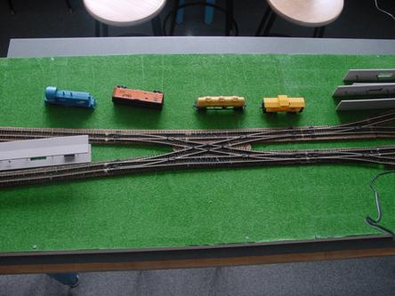
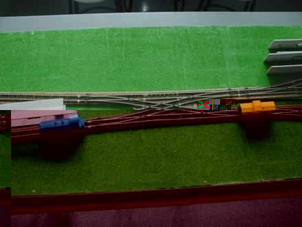
For this milestone, we will create a plan for the train to leave Terminal Station L. When the train leaves the terminal, the Sector 1 switch is in place to allow the train to travel outbound via Sector 2 or Sector 3. You will be creating a Boolean Equation to determine which Sector to use, based on which of the tracks is blocked by railroad cars.
Figure 3: Terminal with switch
Figure 4: Terminal with locomotive (blue) leaving with a blocking car ahead (yellow)
Here are the Boolean Variables you will need to create the equation:
- Let T represent the track that the train is on at the terminal. If T=0, the train is on the bottom track, and if T=1 the train is on the top track.
- Let A represent a train blocking the bottom track after the switch.
- Let B represent a train blocking the top track after the switch.
- If A or B = 0, the corresponding track is free of obstacles. If A or B = 1, the corresponding track is blocked.
- Let S represent the status of the switch. For simplicity, there are only two values. When S=0, any train passing over the switch will stay on course. When S=1, any train passing over the switch will be diverted to the other track.
- Let C represent whether or not you can proceed through the switch to one track or the other. When C=1, the right of way is blocked, and the train cannot proceed. When C=0, the track is clear, and the train can proceed through the switch.
Create a truth table showing every possible outcome. (Hint: How many possibilities should there be?) Create a Boolean equation based upon your truth tables. Create a K-Map and use it to simplify the Boolean equation (if possible). See the Digital Logic Lab in this lab manual for further assistance. Remember, you are solving for S and C.
For the Milestone 1 presentation, prepare a brief description of the problem, what your goals are, and how you will accomplish these goals. In addition, write up a cost estimate of your implementation for leaving Terminal Station L, plus an estimate of the overall project by multiplying this cost by an appropriate factor based on the additional complexity of the overall train layout. The presentation should also include your MS Project chart as well as what you plan to do next.
Milestone 1 Deliverables: A presentation. Prepare a brief description of the problem, what your goals are, and how you will accomplish these goals. Calculate a cost estimate of your implementation for leaving Terminal Station L, plus an estimate of the overall project by multiplying this cost by an appropriate factor based on the additional complexity of the overall train layout, and an MS Project plan.Be sure to include any special features and benefits of your design.
Note: Whenever you revise your drawing(s), your cost estimate, or your MS Project plan, you must include the initial drawing, the initial cost estimate, or the initial MS Project plan, in addition to the revision.
Look Ahead: What tasks do you plan between now and Milestone 2?
Milestone 2
In Milestone 1, we created a plan for the train to leave Terminal Station L, pass through Sector 1, and proceed to either Sector 2, and Sector 3. For this milestone, we will be creating another plan. This time, you will need to create the Boolean logic for the train to travel to, but not through, Sector 4 and Sector 5, and translate that information into a LabVIEW VI.
Here are the Boolean variables you will need to create the equation:
- Let T represent the track that the train is on at the terminal. If T=0, the train is on the bottom track, and if T=1 the train is on the top track.
- Let C represent a train blocking input C.
- Let D represent a train blocking input D.
- Let E represent a train blocking input E.
- Let F represent a train blocking input F.
- If C, D, E, or F = 0, the corresponding track is free of obstacles. If C, D, E, or F = 1, the corresponding track is blocked.
- Let S1 represent the status of the switch at Sector 1. Let S2 represent the status of the switch at Sector 2. Let S3 represent the status of the switch at Sector 3. When S1, S2, or S3 = 0, the train goes straight through. When S1, S2, or S3 = 1, the train crosses over on to the other track.
- Let N represent whether or not you can proceed through the switches to one track or another. When N=0, the path is clear, and the train can proceed. When N=1, all paths are blocked, and the train cannot proceed through any of the switches.
Just like you did for Milestone 1, create a truth table showing every possible outcome, a Boolean equation based upon your truth tables, and a K-Map and use it to simplify the Boolean equation (if possible). Once you have simplified your equations, you can transfer your equations to a LabVIEW VI.
On the front panel, you will need:
- 5 Boolean controls, one for each input (C, D, E, and F), and one to control whether the train is leaving Terminal Station L from the top track or bottom track (T).
- 4 Boolean indicators, one for each sector (S1, S2, and S3), and one indicating No Path (N).
On the back panel, it is up to you how you will program the VI. You may want to consider the use of case structures.
Please refer to Appendix B further down the page for information on how to interface your VI with the Component Testing VI before reading on.
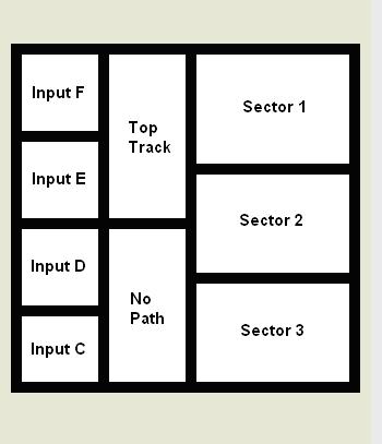
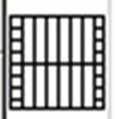
So now that you know you need a connector pattern to interface with the Component Testing VI, you will need to use the following nine node pattern:
Figure 5: Nine node pattern
And connect the pattern in the following manner:
Figure 6: Node assignments of the student’s digital logic circuit
Milestone 2 Deliverables: A copy of your presentation slides that includes a brief description of the problem, your truth tables, screenshots of your VI, what your goals are, and how you plan to accomplish these goals, a revised cost estimate of the overall project based on your solution, your revised MS Project plan, and your signed Component Testing form. Also, include your Boolean Equation.
Note: Whenever you revise your drawing(s), your cost estimate, or your MS Project plan, you must include the initial drawing, the initial cost estimate, or the initial MS Project plan, in addition to the revision.
Look Ahead: What tasks do you plan between now and Milestone 3?
Milestone 3
Prepare a VI that will use your Boolean equations to show how the track switches will be set. Use Boolean switches in the LabVIEW front panel to indicate which track locations are occupied by cars. Use lights on the front panel to indicate which switches are set to divert trains traveling over them. Refer to the Train Electrical Specifications for more information. Refer to Appendix B for more information on how to interface your VI with the Commissioning VI.
Milestone 3 Deliverables: A copy of your presentation slides that includes a brief description of the problem, what your goals are, and how you plan to accomplish these goals, a revised cost estimate of the overall project based on your solution, and your revised MS Project plan. Also, include the screen shots of front and back panels of your LabVIEW program.
Look ahead: What tasks do you plan between now and the completion of the project?
COMPONENT TESTING
Component Testing is a benchmark that is used to let students assess their progress in their Semester Long Design Projects. This is commonly used as a time management tool.
For Component Testing, you will need to interface your VI created from Milestone 2 with the VI located at
C:\SLDP Railroad Train Guidance System\Component Testing.vi
on the PC connected to the train layout. Your TA will test your VI by running your program with various combinations of tracks being blocked.
COMMISSIONING
For commisioning, since you have to go in both directions, you will need to add a switch to your VI to determine what direction to use. On the direction switch, traveling left to right should be a 1 and right to left should be a 0.
Load your VI into the PC connected to the train layout, and interface it with the Commissioning Test VI. The Commissioning Test VI can be located at
C:\SLDP Railroad Train Guidance System\Commissioning Test.vi
on the PC connected to the train layout. Your TA will then place train cars in various locations, and position the locomotive on a track at Terminal Station L. The TA will first test your program using Normal Mode. Set the Boolean switches on your LabVIEW front panel so your VI has this information. When the TA is finished, your VI should read the Boolean switches and locations of the train cars via the VI provided by the EG staff, calculate the proper track switch positions, and output the results to the Commissioning Test VI. This VI will set the track switches according to your specifications. The TA will verify that the path you have established will work. Once your VI establishes a successful path, the TA will drive the locomotive from left to right. After the locomotive arrives on the proper track at Terminal Station R, the TA will rearrange the cars blocking paths for the return to Terminal Station L. Set the Boolean switches on your LabVIEW front panel to indicate this information. Your logic should read the blockage information from the VI provided by the EG staff and set the track switches to the proper position. The TA will verify that you’ve established a good
path, and will drive the locomotive back to the Terminal Station L, arriving on the proper track.
After you have tested your VI with normal running, the TA will then test your VI in Reverse Running Mode. The procedure will be the same as the Normal Mode, with the exception of Reverse Running.
Finally, your TA will test your VI such that it indicates no path correctly. If your VI completes all tests successfully, you will be commissioned.
COMPETITION
At the discretion of the EG staff, you may be competing against other groups in your section. The winner of the competition will be the team that creates the VI that has the locomotive traverse the shortest distance in its outbound and return trips combined, with all teams using the same arrangement of blocking cars. In the event of a tie, the team with the lowest cost will win.
FINAL PRESENTATION
Your final presentation will be a technical briefing, similar to the milestones, plus a sales presentation explaining why MTA New York City Transit should select your company instead of someone else’s. Please include the following:
- A description of the problem
- An overview of your solution
- A description of your company and why it is qualified to successfully do this job
- The truth tables you created
- The resulting logic equations derived and simplified via your K-Map
- Your final LabVIEW programs
- The cost estimate
- Your MS Project from each milestone showing your progress
- A video of the locomotive traversing the layout from left to right and returning
- Why your company is the best choice in awarding this contract
After you deliver your final presentation, you will proceed to the model shop to have your work commissioned, if you are not commissioned already. A signed commissioning statement must be included with the TA copy of your final proposal cover letter.
Final Proposal Cover Letter
Your final proposal cover letter should be prepared according to the guidelines listed under "Technical Communication" secion of this manual. After the cover letter, there should be the following appendices:
- Truth tables
- LabVIEW printouts
- MS Project Schedule
- Cost estimate
EARLY ACCEPTANCE
If you complete your project one week early, you are eligible for a bonus that will be added to your final semester-long project grade. You must submit all deliverables by 5PM one week before your section is scheduled to present (see syllabus for exact date). To commission early, all required information on the form titled Early Acceptance of Semester Project, found on the EG web site, must be approved, accepted, and signed by a TA. The deliverables received early are the ones you will use in your presentation. No adjustments to the deliverables commissioned will be accepted.
LIQUIDATED DAMAGES
If you do not complete all your deliverables and do not commission during the Final Presentation, you will incur liquidated damages as defined in the grading policy.
Appendix A: Train Electrical Specifications:
Output control of the track
Figure 1: Layout of the eight sectors on the train track
Each part of the track is separated into different sectors. The sectors can be classified into two types, X and Y (refer to the diagram). Sectors 1, 4, 5, and 8 are X type and Sectors 2, 3, 6, and 7 are Y type.
There is a Sub-VI that will be provided that will cause the tracks to move depending upon which data is sent to the VI. Only include this Sub-VI in your their logic VI. The Sub-VI has eight inputs which are Boolean named, Sector1 through Sector 8.
For the X type sectors, a Boolean value of True will cause the tracks to be oriented for the train to cross. A Boolean Value of False will cause tracks to be oriented for the train to go straight.
For the Y type sectors, a Boolean value of True will cause the tracks to be oriented for the train to be diverted to the outside track. A Boolean Value of False will cause the tracks to be oriented for the train to be diverted to the inside track.
Input from the track
Figure 2: Layout of the twelve possible positions of train cars on the train track
There are twelve possible locations for train cars which can be located on positions A to L. A Sub-VI will be provided to you that will have twelve Booleans outputs named Input A through Input L. A True will represent a train car being present and a False will represent a car not being present on that position. These outputs will be used as the inputs to your digital logic circuit.
Appendix B: LabVIEW
Note: The following instructions are for your VI that will interface with the commissioning VI. For Component Testing, you will need to use a different pattern. Please refer to the Milestone 2 section for information on what pattern to use, and how to connect the pattern to your VI.
On the Front Panel, there must be 12 Boolean switches to represent the 12 inputs of the train and 8 Boolean lights to represent each of the 8 sectors.
- On the front panel of the LabVIEW program, right click on the connector icon on the top right hand corner icon. Choose Show Connector.
- Right click on the connector icon and select Patterns. Choose the pattern with 28 nodes.
- To assign the Boolean switches and displays to a node, click on the Boolean switch or light on the front panel then click on the node you wish to assign it to.
- If you make an error in a connection, right click the incorrect terminal and select Disconnect This Terminal.
- The 8 nodes on the left side will be for the Boolean switches representing inputs showing occupancy for locations A-H. The 4 nodes on the bottom half of the icon starting from the left will be the inputs for locations I-L.
- Connect the 8 Boolean outputs that represent the orientation of the sector to the 8 nodes on the right side of the icon.
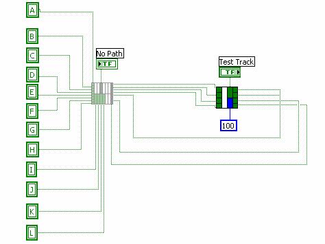
- Replace the faded icon in the program Commissioning Test.vi with your digital logic VI. Right click on the icon and choose replace. Then choose Select a VI and find your VI. Replace it as shown in Figure 3.
- Before testing your digital logic circuit, turn on the power to the middle workbench where the two power supplies are connected.
- Continuously run the Commissioning Test.vi and ensure that the lights on the front panel accurately represent the presence or absence of a train.
- Flip the Reset switch up and down and the track will be preset to the specified orientation.
- Once those parameters are checked, test the digital logic circuit by flipping the Test Track switch.
Figure 1: Twenty-eight node pattern
|
Input |
|
|
No |
Direction |
Top or |
Reverse |
Sector |
|
Input |
Sector |
||||||
|
Input |
Sector |
||||||
|
Input |
Sector |
||||||
|
Input |
Input |
Input |
Input |
Input |
|
|
Sector |
|
Input |
Sector |
||||||
|
Input |
Sector |
||||||
|
Input |
Sector |
Figure 2: Node assignments of the student’s digital logic circuit
The program Commissioning Test.vi for students to insert their logic circuit
Footnotes
1 Metropolitan Transportation Authority website. 2005. Retrieved January 21, 2005. http://www.mta.nyc.ny.us/capconstr/sas/sas_history_1
