Difference between revisions of "Template:SLDP: Microsoft Project"
| Line 1: | Line 1: | ||
== Drawings == | |||
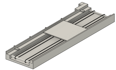
You will be required to draw a CAD model of your device for Milestone presentations and Benchmark assessments. You can use any CAD software to do so. EG1003 uses and teaches Fusion 360 for labs and other SLDPs, and [https://www.autodesk.com/products/fusion-360/students-teachers-educators Fusion 360] is the recommended software for CAD. You can download Fusion 360 for free using your NYU email. Other CAD software such as SolidWorks, Inventor, and Rhino are permitted, however EG1003 does not provide resources in obtaining or learning those programs. | |||
Using your chosen CAD software, create four drawings of the device: front, top, most detailed side, and isometric. Sensors and motors must be included in each drawing. | |||
Each revision of the design must be documented and all changes must be presented during Milestone presentations. | |||
[[Image:RAD_CAD_Drawing.png|400px|thumb|center||Figure 4: Example of CAD Drawing]] | |||
== Diagrams == | |||
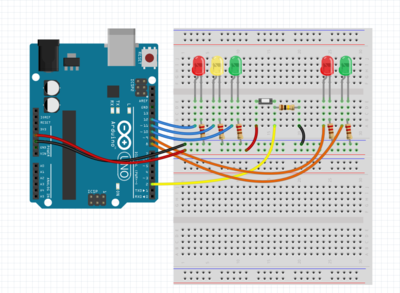
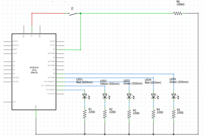
You will also be required to create a circuit diagram and a schematic diagram of your device for Milestones, presentations, and Benchmark assessments. A circuit diagram visualizes a lifelike representation of your circuit, concerning the physical layout of the wires and how they're connected to the components. (Figure 5). A schematic diagram shows the plans and functions of your circuit, but is not concerned with the physical layout of the wires (Figure 6). | |||
[[Image:RAD_Circuit_Diagram.png|400px|thumb|center||Figure 5: Circuit Diagram Example]] | |||
[[Image:RAD_Schematic_Diagram.png|400px|thumb|center||Figure 6: Schematic Diagram Example]] | |||
EG1003 recommends the circuitry modeling softwares [https://www.tinkercad.com/|| Tinkercad] and [http://fritzing.org/|| Fritzing] to fulfill these deliverables. Tinkercad is a free browser-based circuitry software that is especially useful for constructing circuit diagrams with common electrical components. For projects with more complex electrical components, Fritzing is a free circuitry software with an encompassing library of electrical components that is useful for constructing circuit diagrams and schematic diagrams. For a guide on using both softwares, please refer to the [[Virtual Circuit Simulation Guide]]. | |||
== Microsoft Project == | == Microsoft Project == | ||
Revision as of 21:59, 29 January 2021
Drawings
You will be required to draw a CAD model of your device for Milestone presentations and Benchmark assessments. You can use any CAD software to do so. EG1003 uses and teaches Fusion 360 for labs and other SLDPs, and Fusion 360 is the recommended software for CAD. You can download Fusion 360 for free using your NYU email. Other CAD software such as SolidWorks, Inventor, and Rhino are permitted, however EG1003 does not provide resources in obtaining or learning those programs. Using your chosen CAD software, create four drawings of the device: front, top, most detailed side, and isometric. Sensors and motors must be included in each drawing.
Each revision of the design must be documented and all changes must be presented during Milestone presentations.
Diagrams
You will also be required to create a circuit diagram and a schematic diagram of your device for Milestones, presentations, and Benchmark assessments. A circuit diagram visualizes a lifelike representation of your circuit, concerning the physical layout of the wires and how they're connected to the components. (Figure 5). A schematic diagram shows the plans and functions of your circuit, but is not concerned with the physical layout of the wires (Figure 6).
EG1003 recommends the circuitry modeling softwares Tinkercad and Fritzing to fulfill these deliverables. Tinkercad is a free browser-based circuitry software that is especially useful for constructing circuit diagrams with common electrical components. For projects with more complex electrical components, Fritzing is a free circuitry software with an encompassing library of electrical components that is useful for constructing circuit diagrams and schematic diagrams. For a guide on using both softwares, please refer to the Virtual Circuit Simulation Guide.
Microsoft Project
You must create a schedule to manage your time in Microsoft Project. You can learn Microsoft Project by doing the MS Project Skill Builder. This schedule must include all tasks related to the project from the start of the project to Submission. The Microsoft Project schedule should include the following:
- Minimum of 20 tasks
- Milestones should be clearly indicated on the project plan (duration of zero days)
- Each task must include the person responsible for completing the task (resource names)
- Use the "Copy Picture" function to include the project plan in the presentations. Do not take a screenshot
- Gantt chart must be displayed alongside the tasks list (fit onto one slide)
- Gantt chart must clearly show a progress line
- Clearly state during the presentation whether the project is on-time, behind schedule, or ahead of schedule
For help in planning the project, review the manual page Planning Project Scheduling & Costs.


