Difference between revisions of "Disaster Relief Robot (DRR)"
| Line 251: | Line 251: | ||
<p align=center>[[Image:Modular6.gif]]</p> | <p align=center>[[Image:Modular6.gif]]</p> | ||
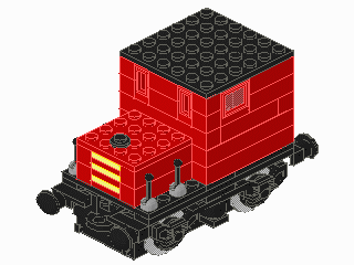
<p>Figure 14: Sample isometric image from MLCad (without part numbers)</p> | <p class=caption>Figure 14: Sample isometric image from MLCad (without part numbers)</p> | ||
<h2>MATERIALS</h2> | <h2>MATERIALS</h2> | ||
Revision as of 22:07, 8 July 2008
RFP*: DRAR (Disaster Relief Autonomous Robot)
* RFP is an acronym for Request For Proposal. Internationally, RFPs are called ITTs, an acronym for Invitation To Tender governmental agencies use RFPs to solicit new business.
INTRODUCTION AND OVERVIEW
In 2008, an Earthquake has damaged a nuclear power plant followed by a hurricane in the area of Bluesville County. The damage done by these disasters led to an emergency shutdown by the nuclear agency.
In order to ensure the safety of the workers in the plant, the president of the nuclear agency Billy Thai issued an RFP for the design and construction of a robot that will perform several tasks to shut down the facility. This disaster relief autonomous robot (DRAR) must be both innovative and cost effective. President Thai anticipates using this robot on all of the power plants in the future if a disaster were to occur.
SPECIFICATIONS
Design a robot using MLCad as your primary design tool. Your team must build a model of your design using the materials provided. A Mindstorms program that will direct the robot's movements must be created. A cost estimate of the robot's components must be provided. All revisions to the original design must be recorded and explained this includes technical design drawings, as well as cost estimates. All revisions to the Mindstorms program must be recorded and explained.
The DRAR must be able to navigate autonomously around the nuclear facility. The robot must perform at least return to base in 5 minutes. The robot must fit in a start area that is 25cm long by 25cm wide. There is no height restriction and all parts of the robot must be within and not overhanging
These specifications must be met for final commissioning. Please refer to the course syllabus for all due dates.
Note: Any student who attempts to alter the course in any way, shape, or fashion (this includes lifting a tile to inspect its design) must meet with the Course Director to explain your attempt at academic dishonesty.
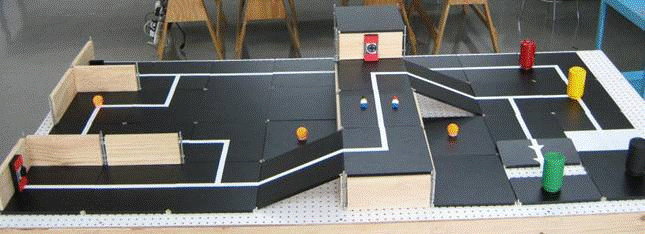
DRAR FIELD
Figure 1: DRAR Navigation Field
Note: The picture above contains one representation of this
project description.
Actual course may be different from the one pictured above,
but similar in objective.
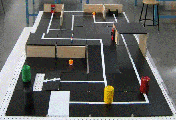
Figure 2: DRAR Navigation Field
Note: The picture above contains one representation of this
project description.
Actual course may be different from the one pictured above,
but similar in objective.
DRAR TASKS
- Cut power to facility – This is a required task. The power must be cut off in order to perform the other tasks.
- Rescue scientists – This is a required task. The scientists have been injured and need to be sent to base for an ambulance.
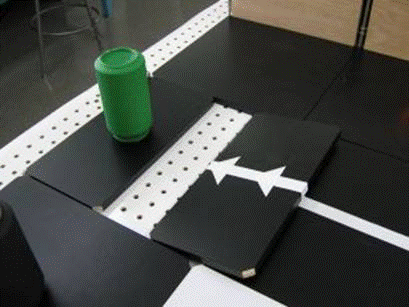
- Secure structure of the facility – Push into place the displaced concrete plate unleveled by the quake under which liquid waste is stored.
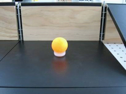
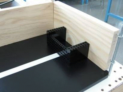
- Refill backup power supply – Bring a fuel cell (ping pong ball) to the power supply container.
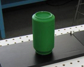
- Dispose nuclear waste – Knock the nuclear waste (green can) off of the course.
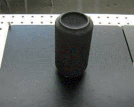
- Dispose empty container – Knock the used up container (black can) off of the course.
The starting point is indicated by the tile in Figure 3:
(Picture to be taken)
Figure 3: DRAR Starting Point
Note: The picture above contains one representation of this
project description.
Actual course may be different from the one pictured above,
but similar in objective.
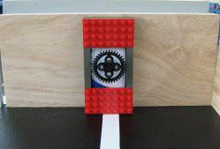
The power switches look like these:
Figure 4: Power Switch
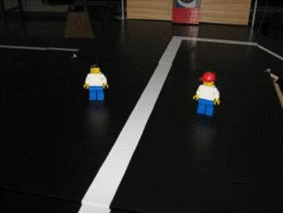
The scientists may be anywhere on the tile, they look like this:
Figure 5: Scientists
Note: The picture above contains one representation of this
project description.
Actual course may be different from the one pictured above,
but similar in objective.
The displaced concrete plate is indicated in Figure 6:
Figure 6: Displaced Concrete Plate
Note: The picture above contains one representation of this
project description.
Actual course may be different from the one pictured above,
but similar in objective.
Fuel cells are located around the DRAR field and must be placed inside the power supply container, they look like this:
Figure 7: Fuel Cell
Note: The picture above contains one representation of this
project description.
Actual course may be different from the one pictured above,
but similar in objective.
Figure 8: Power Supply Container
Note: The picture above contains one representation of this
project description.
Actual course may be different from the one pictured above,
but similar in objective.
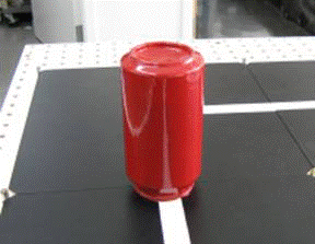
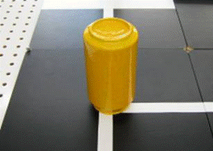
There are different colored cans:
Figure 9: Nuclear Waste
Note: The picture above contains one representation of this
project description.
Actual course may be different from the one pictured above,
but similar in objective.
Figure 10: Empty Container
Note: The picture above contains one representation of this
project description.
Actual course may be different from the one pictured above,
but similar in objective.
Flammable waste containers must be avoided! This means that your robot must not touch this:
Figure 11: Flammable Waste Container
Note: The picture above contains one representation of this
project description.
Actual course may be different from the one pictured above,
but similar in objective.
However, non-toxic waste can be touched by the robot:
Figure 12: Non-toxic Waste Container
Note: The picture above contains one representation of this
project description.
Actual course may be different from the one pictured above,
but similar in objective.
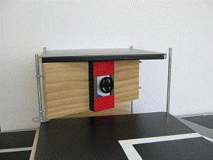
Since the facility was damaged, there may be loose walls:
Figure 13: Loose Wall Power Switch
Note: The picture above contains one representation of this
project description.
Actual course may be different from the one pictured above,
but similar in objective.
Please Note:
During commissioning, the instructors or your TA will make all judgments as to the successful completion of tasks. Protests will not be considered.
Creativity and innovation are always rewarded. Original designs will receive extra credit.
IMPORTANT
A robot has successfully returned when any part of the robot crosses or overhangs the baseline. If the robot is returning an object to base, credit will be received when any part of the object crosses or overhangs the baseline. The object must be in base at the end of the trial run for credit to be received. Therefore, any retrieved objects should be removed from the robot autonomously or by a team member and placed within base right away. Objects knocked out of base accidentally by the robot and not pushed back autonomously do not receive credit!
A team member may pick up the scientists and load them onto the robot by hand. The scientists may be removed from the robot by hand once they are within base. You may NOT touch the robot while you do this.
The robot program may not be altered or switched during any part of the mission. Likewise, the robot must be fully autonomous and therefore cannot be touched by any person during testing. The robot must return to base after it has completed its tasks
EXTRA CREDIT
Extra credit is awarded if the robot:
- Brings additional fuel cells to the power supply container (+2 points for each additional fuel cell).
- Open a 2nd power switch for extra caution (+2 points).
MICROSOFT PROJECT
Your team must create a time management plan using Microsoft Project (MS Project). You can learn Microsoft Project by doing the MS Project Skill Builder contained elsewhere in this manual. This plan must include all tasks related to the project. Each task must be named, assigned duration and assigned to a specific person (or people). You must begin your work by creating an MS Project plan. Follow your project plan throughout the semester. If the team falls behind schedule, explain the reasons for the delays when you present your progress reports, list the steps being taken to get the project back on track, and create a revised MS Project plan.
For help in planning your project, review the page called How to plan the schedule and calculate costs for a project in the section called Material to help you with the project elsewhere in this manual.
There should be at least twenty tasks/subtasks and three Milestones. Milestones should be noted with the duration of "0day". Moreover, the copy picture function included in MS Project Software should be used instead of the print screen function of the computer.
DRAWINGS
A command of MLCad is necessary for you to complete the drawings required for this project. Use MLCad to create four drawings of your robot: front, top, most detailed side, and a drawing of your gear trains. Sensors, motors, and gears must be included in each drawing. All parts used in the robot must be referred to using the part number found in the price list.
Each revision of your design must be documented. This is done by saving the old side view drawing, and assigning a revision number to the new drawing.
NXT Parts
Since NXT is a very recent technology upgrade to Mindstorms, the NXT parts have not been fully reviewed for inclusion in the "official" parts library for MLCad. There are unofficial versions of the parts available for use in MLCad. You can download the parts using the following links:
- Watch this space for links
Figure 14: Sample isometric image from MLCad (without part numbers)
MATERIALS
The following materials will be provided:
- Mindstorms NXT part kit
- One NXT
- Sensors
- Motors
Additional materials can be supplied by your TA.
COST ESTIMATE
Once a robot design is complete, a cost estimate must be generated that specifies the cost of all the materials and labor required for the construction of your design. Tabulate this cost information clearly in an Excel spreadsheet, using the materials cost list provided. You can get help in calculating the cost by reviewing the page called How to plan the schedule and calculate costs for a project in the section called Material to help you with the project elsewhere in this manual. The costs for the parts can be found on the page Price list for Lego parts for robot projects in the Material to help you with the project section elsewhere in this manual.
Note: You should only use the materials contained in the Price list for Lego parts for robot projects. If you want to use other parts, get permission from your faculty member to do so, and also to determine the cost of the parts you want to use that are not in this price list.
Have all the materials and parts used categorized in different groups instead of including individual parts. Make sure to include the units of each part used in a group and total them up for that individual group. Moreover, the cost of labor should be included. You can get help on the labor cost by reading the page How to plan the schedule and calculate costs for a project in the section called Material to help you with the project elsewhere in this manual.
MILESTONES
As you work on your project, you will be required to present periodic reports on your progress. We call these Milestones. All the items assigned in each Milestone are called deliverables. These deliverables often consist of a combination of written submissions, presentations, and demonstrations.
Milestone 1
Prepare a preliminary sketch of your design, a cost estimate, and an MS Project plan.
Look Ahead: What tasks do you plan between now and Milestone 2?
Milestone 1 Deliverables: A presentation. Include the preliminary sketch, cost estimate, and MS Project plan. Include a brief description of the robot and any special features and benefits of your design.
Note: Whenever you revise your drawing(s), your cost estimate, or your MS Project plan, you must include the initial drawing, the initial cost estimate, or the initial MS Project plan, in addition to the revision.
Milestone 2
Using MLCad, prepare four views of your latest design: front, top, most detailed side, and an isometric drawing. Create an MLCad drawing of your gear trains. Complete your latest Mindstorms program and your latest MS Project plan reflecting any schedule changes. Finally, calculate a revised cost estimate. A signed Component Testing Form must be submitted to your Recitation TA.
Look Ahead: What tasks do you plan between now and Milestone 3?
Milestone 2 Deliverables: A copy of your presentation slides that includes four views of your design using MLCad: front, top, most detailed side, and an isometric drawing; an MLCad drawing of your gear trains; your Mindstorms program; a revised cost estimate; your revised MS Project plan; and your signed Component Testing Form.
Note: Whenever you revise your drawing(s), your cost estimate, or your MS Project plan, you must include the initial drawing, the initial cost estimate, or the initial MS Project plan, in addition to the revision.
Milestone 3
Using MLCad, prepare four views of your latest design: front, top, most detailed side, and an isometric drawing. Create an MLCad drawing of your gear trains. Complete your latest Mindstorms program and your latest MS Project plan reflecting any schedule changes. Finally, calculate a revised cost estimate.
Look ahead: What tasks do you plan between now and the completion of the project?
Milestone 3 Deliverables: A copy of your presentation slides that includes four views of your design using MLCad: front, top, most detailed side, and an isometric drawing; an MLCad drawing of your gear trains; your Mindstorms program; a revised cost estimate; and your revised MS Project plan.
Note: Whenever you revise your drawing(s), your cost estimate, or your MS Project plan, you must include the initial drawing, the initial cost estimate, or the initial MS Project plan, in addition to the revision.
FINAL PRESENTATION
The exact specifications for your final presentation will be provided by your instructor. Some of these requirements will be: the features and benefits of your design, project specifications, all drawings, Mindstorms programs, cost estimates, and your completed MS Project. After you deliver your final presentation, you will proceed to the Model Shop to have your work commissioned (tested). A signed Commissioning Statement must be included with your final presentation materials.
FINAL SUBMISSION
Your project should be submitted as a folder containing the following deliverables:
- Component testing statement
- Commissioning statement
- Hardcopy and CD containing:
- Final presentation
- Cover page and table of appendices.
- Appendices:
- Final Mindstorms program
- Initial sketch
- All the drawings of your final design
- Video
- Final MS Project Schedule
- Final Cost estimate
- Resume(s)
EARLY ACCEPTANCE
If you complete your project one week early, you are eligible for a bonus that will be added to your final semester-long project grade. You must submit all deliverables by 5PM one week before your section is scheduled to present (see syllabus for exact date). To commission early, all required information on the form titled Project Submission Form, found on the EG web site, must be approved, accepted, and signed by a TA. The deliverables received early are the ones you will use in your presentation. No adjustments to the deliverables commissioned will be accepted.
LIQUIDATED DAMAGES
If you do not complete all your deliverables and do not commission during the Final Presentation, you will incur liquidated damages as defined in the grading policy.
