Sandbox/Filters
Electronic Circuits: Introduction to Electronic Filters
Overview
Electronic filters are used to filter specific frequencies. For AM (amplitude modulation) and FM (frequency modulation) radios, specific frequencies are filtered. By tuning a radio to a particular station, it is isolating a certain frequency. The filter selects the station chosen by the listener from the hundreds of different stations that are broadcasting. How does the filter accomplish this?
To understand how filters work, it is important to understand the elements that make electrical filtering possible. Signals that occur naturally are composed of many frequencies.
For example, the human voice is composed of frequencies ranging from 0–4kHz. A signal consists of a primary frequency, called a base frequency, plus additional multiples of that frequency with different loudness called harmonics. Different devices will have different harmonics. This is why when a trumpet and clarinet both play the same musical note they sound different — their harmonics are different. We hear the base frequency plus the harmonics of these instruments. Rock guitars have their distinctive sound by adding harmonics to the note they play.
Radio waves have a base frequency, and the audible information is contained in adjacent frequencies called sidebands.
Voltage, or electromotive force, and frequency are the building blocks of an electrical signal. Voltage is a force that propels electrons through a medium. Current is the amount of electric charge flowing past a specified circuit point per unit time. Frequency is the rate at which the signal repeats itself. The gain of a circuit is the ratio of its output power compared to its input. For devices that do not produce energy, such as the filters in this lab, the gain cannot be positive. Devices such as transistors and other amplifiers are needed to achieve positive gain.
A filter is a circuit that shapes and controls the bandwidth of a signal; bandwidth is the range of frequencies that the filter allows to pass. For example, when the bass of an audio amplifier is turned up, that operates a filter that passes the low frequencies more than the high frequencies. Also, when a radio is tuned, it is using a filter that allows the base frequency plus the sidebands of the desired station to pass, but not other stations.
The filters that will be built in this lab are composed of resistors and capacitors. A resistor resists the flow of electrons by converting some of the electric energy to heat. The voltage across a resistor obeys Ohm's Law: V = IR, where I is the current and R is the resistance. Varying the frequency of the voltage will not affect the voltage across the resistor.
A resistor is designed to impede the flow of electricity and dissipate electrical energy in the form of heat. Resistors work by having the electricity flow through a poor conductor such as carbon. The unit of resistance is the Ohm, named after George Ohm, and is represented by the capital Greek letter Omega (Ω).
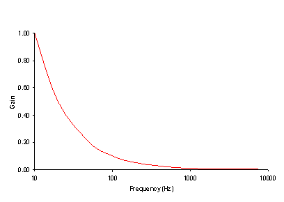
Capacitors are metal plates that are separated from each other, allowing electric charge to accumulate on the plates. These plates store energy rather than dissipate it, like a resistor. For DC voltage, provided by a device like a battery, the plates will gather charge, and once the plates are charged, will no longer pass current, so the capacitor looks like an open circuit, where nothing is connected. For high frequencies, the charge can quickly gather and dissipate off of the plates, allowing current to flow through the capacitor freely, making the capacitor behave like a short circuit. The unit of capacitance is the Farad, named after Michael Faraday, and is represented by the capital letter F. The relationship between the voltage across a capacitor and varying frequencies is shown in Figure 1.
Inductors, also known as coils or chokes, are coils of wire that allow the current through a wire to form a magnetic field. Like capacitors, inductors store energy, but in the magnetic field instead of on plates, and its behavior is the opposite of a capacitor. For DC voltage, the current will make a stable magnetic field and the current will flow freely, making the inductor look like a short circuit. At high frequencies, the magnetic field does not have time to form before the current reverses and the field collapses, causing the inductor to resist the current flow, looking like an open circuit. The unit of inductance is the Henry, named after Joseph Henry, and is represented by the capital letter H. The relationship between the voltage across an inductor and varying frequencies is shown in Figure 2.
The elements of filters, such as resistors, capacitors, and inductors, are connected by conductors (wires) that carry electrons between these devices. The voltage is the same throughout the entire conductor, so the voltage across the two ends of the conductor is zero.
How the components are connected is shown using a schematic diagram. Each component is represented by a symbol, and the connections between components are represented by lines. The symbols are designed to represent the physical characteristics of the components. A resistor is represented by a zigzag line showing how the electricity's path is impaired. A capacitor is shown as two parallel lines, representing its plates. An inductor is shown as a series of looping lines, representing the coils of wire. The schematic diagram symbols for these components are shown in Figure 3.
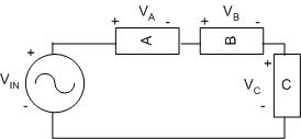
Different combinations of resistors and capacitors allow engineers to build different kinds of filters to perform specific tasks. Resistors, inductors, and capacitors can be arranged in three different ways. In a series circuit, the element's conductors are connected end to end. The current in a series circuit remains the same in all the electrical elements. In a series circuit, as shown in Figure 4, the sum of the voltages across each element is equal to the voltage of the power source (VIN = VA + VB + VC).
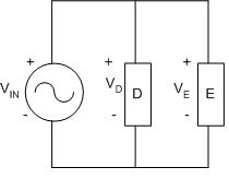
In a parallel circuit, as shown in Figure 5, the element's conductors are connected at opposing ends. The current that is supplied by the voltage source equals the current that flows though elements D and E. The voltage across the elements that are parallel is the same (VIN = VD = VE).
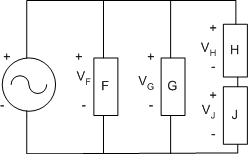
Series and parallel circuits can be combined, as shown in Figure 6:
The voltage across the top and bottom connectors is the same, so (VIN = VF = VG = (VH + VJ)).
To produce a graphical representation of the characteristic behavior of a circuit being analyzed, it is necessary to graph the gain of the circuit versus the frequency of the electrical signal. Gain is a measure of the power produced by the circuit, measured in decibels, and is calculated using the following formula:
A 3dB drop of signal power is the point at which the signal power is half of its original value. The frequency corresponding to this -3dB point is also called the cutoff frequency of the filter. Note that since the filters built in this lab only contain passive components, the output voltage cannot be greater than the input voltage so the gain will never be a positive number because the logarithm of a number less than or equal to one is taken.
In the preceding formula, for the gain to be -3dB, VOUT must be VIN divided by = 1.414, or more easily written as VOUT = VIN / 1.414. The -3dB point of a circuit is the frequency that causes the output voltage to be 0.707 times the input voltage.
Types of Filters
Once the electrical filters are built according to the specifications in this manual, the filter type must be identified. In this lab, there are three possibilities.
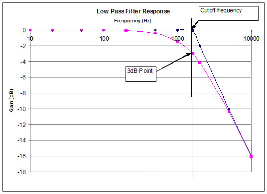
Sometimes, it is beneficial to remove the high frequency components from a signal because this is where unwanted noise frequently exists. To do this, a low-pass filter is used. It passes the low frequencies while blocking the higher ones. The low-pass filter shown in Figure 7 has a gain that drops to -3dB at 1590 Hz, which is its -3dB point and corresponding cut-off frequency. The filter has a bandwidth of 1590Hz and it only allows frequencies from 0Hz to 1590Hz to pass through. Figure 7 shows the characteristic behavior of a low-pass filter. A trend line showing the response of the filter is also shown. Note that for low frequencies, the gain is 0dB, meaning that the output equals the input. The filter suppresses high frequencies, as shown by the trend line on the right.
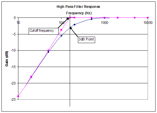
A high-pass filter passes the high frequencies, but blocks the low ones, the opposite response of a low-pass filter. The -3dB point for this filter is 160 Hz. This is determined using the same method used for the low-pass filter. Figure 8 shows the characteristic behavior of a high-pass filter as well as the trend line and its cutoff frequency. This filter has a bandwidth of 160 Hz to infinity and that the filter only allows frequencies greater than 160 Hz to pass through.
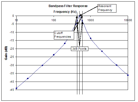
A band-pass filter only allows a certain range of frequencies to pass through and blocks all other frequencies. The frequency of the highest response point is called the resonant frequency, and for an ideal filter will be 0dB. This type of filter has two -3dB points, one above the resonant frequency and one below it, and so two cutoff frequencies. The difference in these two cutoff frequencies is called the bandwidth of the band-pass filter. Figure 9 shows the characteristic behavior of a band-pass filter.
The band-pass filter shown in Figure 9 has a resonant frequency of approximately 500Hz and -3dB points with cutoff frequencies of approximately 400Hz and 600Hz. The bandwidth of this filter is approximately 600Hz-400Hz, or 200Hz.
The opposite of a band-pass filter, which rejects a specific range of frequencies and passes the others, is called called a notch filter. Notch filters are frequently used to remove interference from a desired signal, but will not be used in this lab.
The filters here are ideal filters and show total power transfer of 0dB at their maximum response. Real filters frequently show some losses and may have a maximum response less than 0dB. The -3dB point is still defined according to the formula shown above.
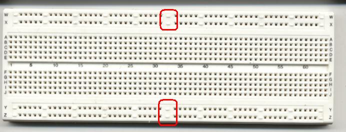
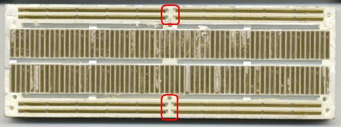
A breadboard will be used in this lab. Breadboards have horizontal and vertical connectors. The front of the breadboard is shown in Figure 10a. The back of the breadboard, with its protective cover removed showing the internal connections is shown in Figure 10b.
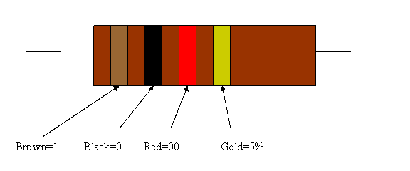
To identify the resistors, look at the colored bands. Hold the resistor horizontally with the three bands that are close together to the left, as shown in Figure 11. The first two colors determine the first two digits of the resistance, and the third band determines how many zeroes to add. Each colored band represents a particular number.
| Color | First Band | Second Band | Third Band |
|---|---|---|---|
| Black | 0 | 0 | × 1 |
| Brown | 1 | 1 | × 10 |
| Red | 2 | 2 | × 100 |
| Orange | 3 | 3 | × 1000 |
| Yellow | 4 | 4 | × 10000 |
| Green | 5 | 5 | × 100000 |
| Blue | 6 | 6 | × 106 |
| Violet | 7 | 7 | × 107 |
| Gray | 8 | 8 | × 108 |
| White | 9 | 9 | × 109 |
The fourth band indicates a tolerance of the resistor, which means how close its actual resistance will be to the value indicated by the bands:
| Color | Tolerance |
|---|---|
| Gold | 5% |
| Silver | 10% |
| No band | 20% |
As an example, a 470kΩ resistor with a 5% tolerance would have color bands of yellow, violet, yellow, and gold.
For capacitors, the value is stamped on the capacitor, especially if the capacitor is large. Most capacitors have very small values. For small capacitors, the most common ranges are microfarads (shown as μF), nanofarads (shown as nF), and picofarads (shown as pF). The following conversion table may help you understand how these ranges relate to each other:
1 μF=103nF=106pF
1 nF=103pF
Sometimes the value is coded. The following rules are commonly used in marking values on capacitors:
- If there are only two digits on the capacitor, the value is in picofarads (nF)
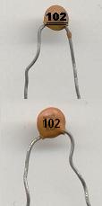
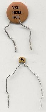
- For three digits, the first two digits of the number are the overall value of the capacitor, and the third is a power of 10, with the overall value being in picofarads. For example, a capacitor with a value of 103 would be 10*103 picofarards, or 0.01 nanofarads. To make this a little easier, the following table might be helpful:
| CODE / Marking |
µF microfarads |
nF nanofarads |
pF picofarads |
|---|---|---|---|
| 100 | 0.00001 | 0.01 | 10 |
| 101 | 0.0001 | 0.1 | 100 |
| 102 | 0.001 | 1 | 1,000 |
| 103 | 0.01 | 10 | 10,000 |
| 104 | 0.1 | 100 | 100,000 |
| 105 | 1 | 1,000 | 106 |
| 106 | 10 | 10,000 | 107 |
| 107 | 100 | 100,000 | 108 |
- Finally, capacitors might use a series of colored bands, like resistors, with exactly the same meaning, except the units are in picofarads instead of ohms.
Also, where there are digits on the capacitor, there might be a letter following the digits. This indicates the tolerance of the capacitor according to the following table:
| Letter Code | Tolerance |
|---|---|
| C | ±0.25pF |
| D | ±0.5pF |
| F | 1% |
| G | 2% |
| J | 5% |
| K | 10% |
| M | 20% |
| Z | -20%/+80% |
The following figures show two capacitors. Use the preceding tables to verify their values.
For inductors, the value is stamped on the inductor.



 = 1.414, or more easily written as VOUT = VIN / 1.414. The -3dB point of a circuit is the frequency that causes the output voltage to be 0.707 times the input voltage.
