Prototyping Guide
Introduction
What is Prototyping?
It’s in the name itself – “Proto” meaning “early” and “type” meaning “thing.” A prototype is an early version of the product that is made cheaply and efficiently to prove that your idea actually works (we call that “proof of concept”). You don’t want to waste money making something useless.
“Ideation” and “Brainstorming”
Before you get to the prototyping stage, you have to figure out what it is you’re making. This is the “Ideation” stage. A good strategy here is to start from your problem and work towards a solution. Ask yourself, “What’s an issue people are dealing with? Who is the underrepresented consumer? Where is there a gap in the market?” In fact, don’t just ask yourself, ask other people from diverse backgrounds with unique experiences. Do research to see what’s already out there. Look critically at the world around you.
Once you’ve answered the “what should it do,” prototyping answers the “How will it work?” (This can refer to the entire product or a specific mechanism within the product).
A few key questions are:
What conditions will my design experience?
This includes temperatures, loads (tensions, compressions, shear forces), repetitive motion, friction, human interaction, contact with body parts, contact with liquids, rotations, and torque.
What dimensions will my design need to be?
Does it have to be wearable? Does it have to stand on its own? Does it have to fit a mid-sized cat inside it?
What components will my design need?
This includes sensors, motors, microcontrollers, cameras, LEDs, LCD screens, micro-computers (like Raspberry Pi’s), speakers, and any and all electrical components which your physical design must house.
And, most importantly, how much time and money do I have?
In EG 1004, you usually have three months and 100 dollars. This greatly impacts what you can reasonably use in your prototype.
Design → Computer-Aided Design
CAD, or Computer-Aided Design, has two advantages: The first is to make neat, precise representations of a physical product before construction, which allows you to test the viability of a design before you break out the hack saw. The second is to generate files that can be 3D printed, laser cut, or CNC milled.
It is also useful to use CAD software (like Fusion 360, TinkerCAD, Eagle, or Fritzing) to design and test the circuit that connects your components, and creates a neat, legible representation of it for reference.
An additional realm of CAD is Building Information Modeling software, also referred to as BIM. BIM software and facilitators (like Revit and AutoCAD respectfully) enable users to design, simulate, collaborate, and budget structures prior to implementation and construction.
Creation → Manufacturing Methods
Below you’ll find a list of possible manufacturing methods available to you. The ones you’ll use depend on the specifications of your design. For example, if it’s a housing unit made out of large, flat pieces, laser cutting might be the right method, because it’s primarily two-dimensional. If it’s a small, light device with a unique shape, 3D printing could be useful since it builds the model layer by layer out of polymer filament. If it needs to be heat resistant or undergo friction, CNC milling might be helpful because there’s a broader range of possible materials. If it’s bulkier but needs to be tough, woodworking is a viable option. Soft, flexible, cozy, and generally inviting? Try sewing.
Do I have to design everything from scratch?
Don’t reinvent the wheel; plenty of components already exist (for example: water pumps, safety goggles, a large broom, an insulated mug, a succulent, pieces of foam pool noodles) that can be used in a prototype. This guide covers the manufacturing of original parts custom-made for the unique needs of your product.
To Solder or not to Solder, that is the question
Soldering is a method of creating permanent connections within a circuit onto a flat protoboard. A soldered circuit is usually much more compact than one using a breadboard and wires for temporary connections. The components can be connected directly using much smaller lengths of wire or lines of conductive metal connections known as “track solder.” This is especially useful in wearable devices and other designs that need to be picked up and handled or moved around, where a temporary connection would be too fragile.
General Tips
- Have a plan. Know your dimensions, know your circuit diagram, know your needed components, and know your environments.
- Research, research, research.
- Be ready and willing to learn.
- Start with the simplest solution first.
- It’s okay to pivot. Sometimes the original design will hit snags nobody could anticipate. Adapt, find a new approach, go back to the ideation stage if you need to.
- It’s an iterative process. Things will probably never work the first, second, or third time.
- If you get stuck, don’t be afraid to reach out to other people.
- Have fun and be yourself.
Manufacturing Methods
The primary manufacturing processes available to EG 1004 students are listed below:
| Name | Advantages | Disadvantages | Requirements |
|---|---|---|---|
| Basic 3D Printing (FDM) (PLA is the default which is hard and inflexible, TPU, which is more rubbery and bendable, is available upon request) | Advantages: cheap, relatively easy to learn, freedom of design in shape | Disadvantages: plastic material, precision of about 0.5 mm realistically, designs built layer by layer from single extrusion onto a plate so be mindful of holes, overhangs | Print must be approved by Protolab TAs |
| Soldering | Advantages: Permanent connections, neater, compact circuit, durability/longevity | Disadvantages: Difficult to undo once soldered, errors can lead to unusable circuit or damaged components | Additional Training from EG1004 Open Lab required |
| Name | Advantages | Disadvantages | Requirements |
|---|---|---|---|
| Basic 3D Printing – PLA available, TPU available, Water soluble support PVA available | Advantages: See description above, opportunity to operate a 3D printer independently | Disadvantages: See description above, strict time limits at the MakerSpace, no one will retry your print if it fails unlike in the protolab | Only MakerSpace Safety Training and Introduction required (this training is an EG1004 course requirement) |
| Woodworking | Advantages: Toughness, creative freedom, no need for software or machinery | Disadvantages: Slack of precision, limitations in possible shapes, possibility of injury | Training recommended for power tools but not mandatory; No reservation needed; material may need to be purchased |
| Sewing | Advantages: Good life skill, fabric use, flexibility, done by hand | Disadvantages: can be difficult to learn, harder to design/represent in CAD. | Training recommended for machines but not mandatory; no reservation needed; material may need to be purchased; (scrap is usually available for free) |
| Laser Cutting | Advantages: works for larger scale pieces than 3D printed designs, strong and rigid, precise. | Disadvantages: limited to 2D, may require Adobe Illustrator | Requires additional training; material sheets may need to be purchased; Reservation needed for machines |
| Advanced 3D Printing (SLA) | Advantages: very precise, durable resin material, uses a laser which allows for intricacies in shapes without the need for support/adhesion layers | Disadvantages: More expensive, harder to operate, often unnecessary depending on the complexity of the design | Requires additional training; material bricks may need to be purchased; Reservation needed for machines |
| CNC Routing & CNC Milling | Advantages: Subtractive, not additive, can use metals and waxes, able to do PCB (Printed Circuit Board) manufacturing | Disadvantages: Additional software skills (Eagle), more expensive | Requires additional training; material bricks may need to be purchased; Reservation needed for machines |
Example Projects
The following projects are example uses of what one can manufacture using CAD and some of the methods discussed above.
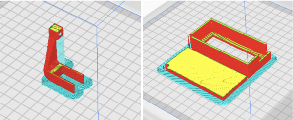
These are devices designed to hold electrical components and attach them to the rest of the build.
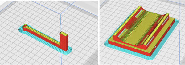
These are designs that interact with the surrounding environment. On the left is a swiping arm attached to a stepper motor which can rotate and provide a delicate push. On the right is a unit molded to the shape of a human wrist. The slits on the side are for fabric straps to secure the unit onto the user.
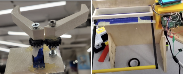
The claw uses both 3D printed parts and standard screws, nuts, and bolts as connectors. The curtain has a woodworked (sawed and screwed) unit with 3D printed attachments.
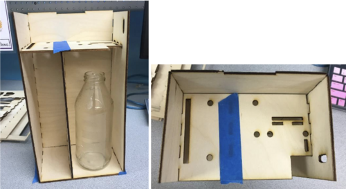
This is a unit assembled using laser cut parts; the holes in the top are for wires and sensor connections.


