MLCad Skill Builder
Objective
In this exercise, you will be introduced to additional software used to design your robotic systems for your semester long project (SLDP). You will learn the basic design methods using MLCad (Mike’s Lego Computer Aided Design), and through this, the needed design for your SLDP will be met.
Overview
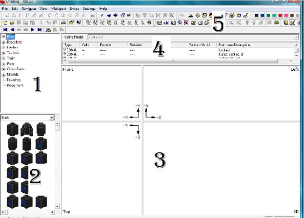
The graphical user interface should look like this with minor differences as shown in Fig 1. The main window is divided into 5 sections as labeled in Fig 1.
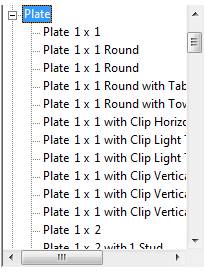
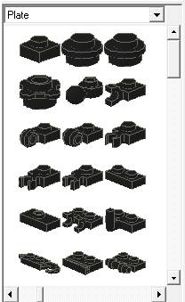
The first section allows for the selection of different types of Lego pieces. By selecting this section, pictures of each piece Is shown in section two, while in section one, the names of each corresponding piece is shown. For example, while clicking plates, you will notice that a different display for section two is shown and each pieces of plates named in the drop down box under the selection of the plates is shown.
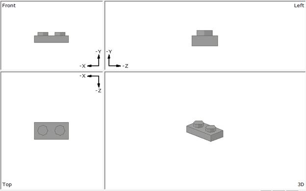
Section three of the graphical user interface is where all construction takes place. In this section, there are 4 perspectives which are left view, front view, top view and 3D view. In this section, all displays are shown and your completed project will be viewed there.
The fourth section displays information about each piece placed on the construction area; information such as type, color, position and etc. This is shown below in Fig 5.
The tool bar is displayed in section 5, this area allows for manipulation of the pieces. For example, you can zoom in, change colors and etc. By playing with this section, you can customize your design to look the way you want it to.
The menu bar consists of many of the needed commands. It allows for the changing of modes, by going to settings, you can change the modes such as the zoom mode, which allows only for zooming, the pan mode which allows for a movement of all pieces at once, the view mode which allows for the viewing of the project and the last one which is the edit mode, allows you to change, edit each piece and add pieces to your design. The edit piece is where you want to be when beginning a new project.
MLCad Exercise
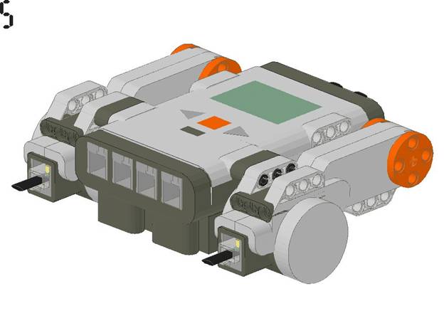
Completely assemble the 3D layout of one NXT brick, two motors and the required connectors (two 1 by 3 technic liftarms).
Exercise 1
Open MLCad, once open, go to section 1 and click on Electric.
After clicking on Electric, scroll down to Electric Mindstorms NXT with rechargeable battery or go to section two to find a picture of the NXT brick. Next you click, hold and drag the NXT brick to top view of the construction area (Section 3). Ones you have finished this step, there should be a NXT brick in all views of the construction area.
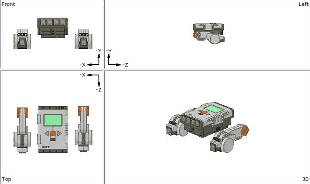
Next you look for the two motors in the same search (clicking Electric and looking for Motors in the drop down display on either section one or section two of the graphical user interface) then click, hold and drag each motor onto each side of the NXT brick as shown below.
The next step is to align the motors with the NXT brick as shown below. After completing this, more pieces are needed to connect the motors and the NXT brick.
Note: The 3D view is the only one that allows for the rotation of all the pieces at once in any direction. The other two parts can only be moved together by selecting all parts, which is done by pressing control and then clicking on what you parts you want to move together. Also each view can be zoomed into by using the middle scroll on your mouse or by going to settings and pressing zoom, which allows you to zoom in/out at different values.
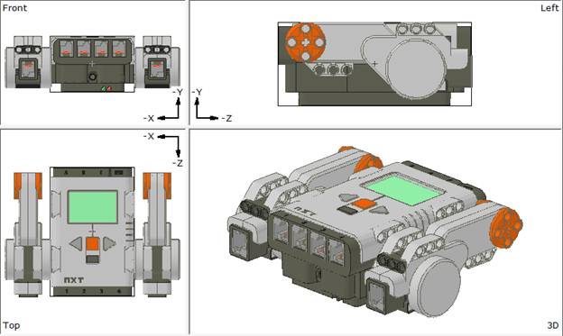
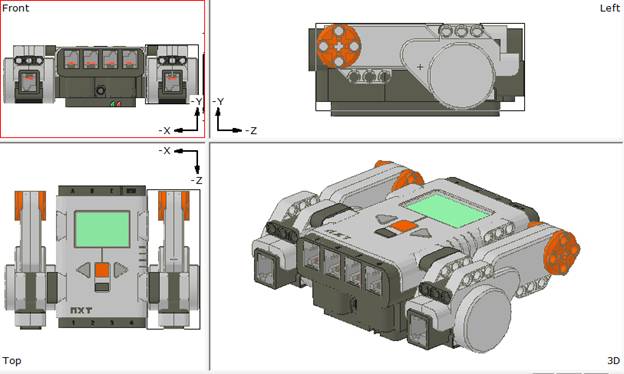
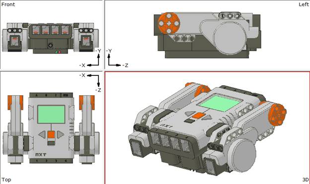
Once aligned it should look like the figure below.
Next you must look for the (1 x 3) Technic Liftarm which is located in the first section under Technic. Under this you can drag two of them onto the top view. You will notice you don’t want the two Technic Liftarm to be in that view. You can rotate it to the view you want it by using the transformation bar in the tools area (section 5).
After placing each Technic Liftarm in the right location, make sure you change the color to gray by using the Colorbar.
Now you should have a drawing similar to the one pictured to the right.
Next, place 6 Technic Pin Long on the top view. Rotate and place in the position shown in Exercise 1. Change the color to the appropriate color.
You have now completed Exercise 1.
