Lego Digital Designer Skill Builder
Objective
In this exercise, you will be introduced to additional software used to design your robotic systems for your semester long project (SLDP). You will learn the basic design methods using Lego Digital Designer in order to create a 3D model of the chassis of a robot. After practicing the skills learned in this tutorial, you will be able to create models of your own robot to include in reports and presentations.
NOTE: Some instructions and pictures on this page are outdated. We are working on updating it. Please ask a TA if you need any further help with Lego Digital Designer. Thank you for your patience!
Background Information
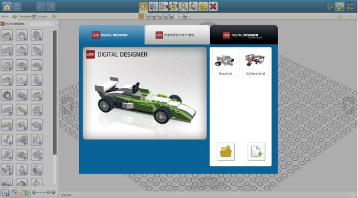
After opening Lego Digital Designer, you will see a window showing three different build options. Each of these options, Digital Designer, Mindstorms, and Digital Designer Extended, provide the user with a different palette of lego pieces to choose from. Select the Mindstorms tab in order to access the full range of what you will use to physically construct your robot. Press the free build icon on the lower right hand side to begin designing.
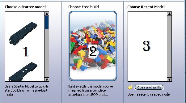
In each building option there are three categories. First, there is the Starter Model which allows you to choose from different starter models and build from there. The second is the Free Build, which allows you to build from scratch. The third of the three categories is the Recent Model which shows the models you have worked on and you can continue to build from our old designs.
Overview
Now you will begin by going to factory building option. Then, you will select the free building type and now you should be in the build mode of Lego Digital Designer. In build mode, you are able to build on this mode. On the top right hand side you should see Figure 3. The first icon is the build mode, while the second it the view mode which allows you to watch your model in different environment, the third icon is the building guide which shows you how to make it in real life.
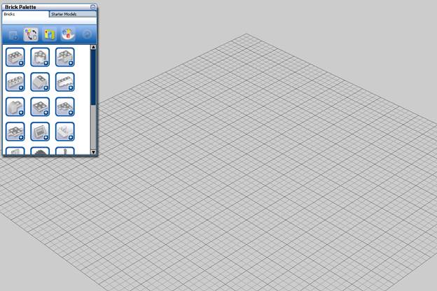
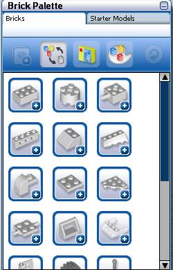
In Figure 4, you will notice there is a plane which is called the scene (this is where you build your model). The second part of the figure shows the Brick Palette. The Brick Palette shows you all the bricks you are allowed to build with in the current theme. In the Brick Palette, you will notice that they are divided into different sections based on the type of brick; these different sections are called dividers. By clicking on one of the dividers, you will notice there is a drop down box which shows different types of bricks in that group based on the design and function. By clicking on the collapse divider button, you can collapse the dividers. The icon the one right side of the collapse divider is called the color slider which allows for the showing of each piece in the different colors they appear in or it also allows for the display of each brick without displaying colors. The next icon called the Filter brick by box allows for the choosing of pieces from a specific Lego box set. The fourth icon called Filter by Color allows you to choose a color to build in. Ones you filter by either using colors or Lego sets, the last icon on the right called Turn off filter allows you to turn off the filter.
The Tools Palette below shows you all the tools you can use for your model. The first of these tools is the single selected tools which allow you to select on brick at a time. After clicking on this tool, a slide bar will appear (only if you have more than one brick on the scene), you can now choose to select more than one brick at a time by different categories. The next tool is called the Clone tool, which allows you to copy each piece by clicking on it. The next tool is called the Hings tools, which is used to move parts of bricks with moving parts. The Paint tool allows for the changing of colors or materials of each brick. The last of the tools allows for the deletion of each by clicking them.
The Camera controls allow you to zoom and display the view points around you model. By using the up and down arrow you can rotate over and below the object, and same goes to the side arrows. The plus and minus buttons allows for the zooming in and out. By clicking the center button, you can center your project.
Lego Digital Designer Exercise
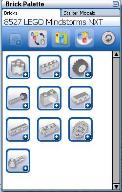
In order to begin, you must first select filter bricks by boxes. After selecting this, you will then choose the 8527 LEGO MINDSTORM NXT. Once selected, you should see that the Brick Palette displays fewer dividers than before as shown in the figure below.
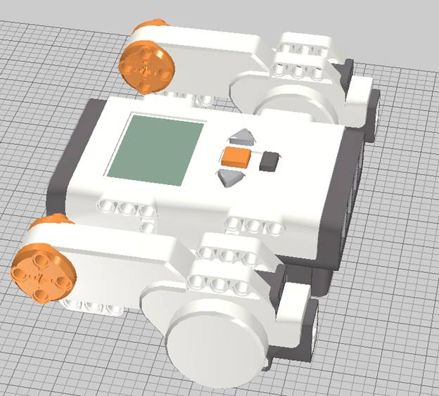
You will start this project by going to the fifth divider and selecting the NXT brick and placing it on the scene. After placing it, you will now select a motor and then use the Clone tool in the Tools Palette to place a second motor on the scene. You should now have two motors and a NXT brick on the scene as shown below.
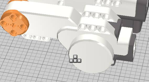
Now you must rotate each of the motors by using the Hings Tool also found in the Tools Palette. Next, move the two motors in the right position. In order to check if the holes are lined up, use the camera view to do so. In order to rotate, make sure you click and turn the green arrow showing you the direction for which you can rotate in. By using the single select tool (arrow) found in the Tools Palette, you can move the motors back to the original position. In order to flip the pieces, you must click and hold until 4 arrows shows up as shown below, by using the up, down, left and right key on your keyboard you can rotate the brick the way you want.
Note: In order to speed up the process, you might want to place one motor on the scene and then rotate and fix its position before using the clone tool, this will save you time because you don’t have to fix the position of the second motor.
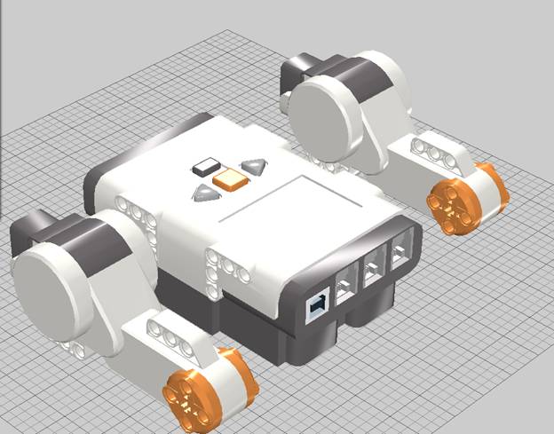
Below is the aligned design.
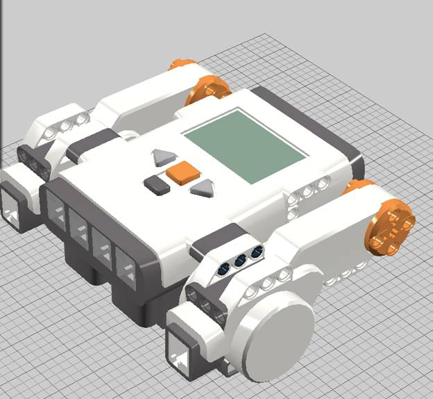
Next, you must place two 1 x 3 Technic found in the sixth divider of the Brick Palette, and six Connector Pegs found in the eighth divider of the Brick Palette on the scene. Once placed, rotate if needed and connect all parts. When connected you should notice green lines indicating fit. Now you should have should have the following figure below.
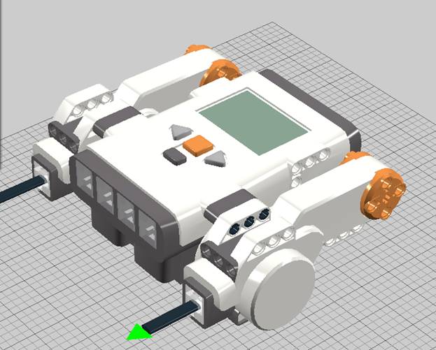
Now you can place the two wires into the motors by placing a wire from the fifth divider from the Brick Palette.
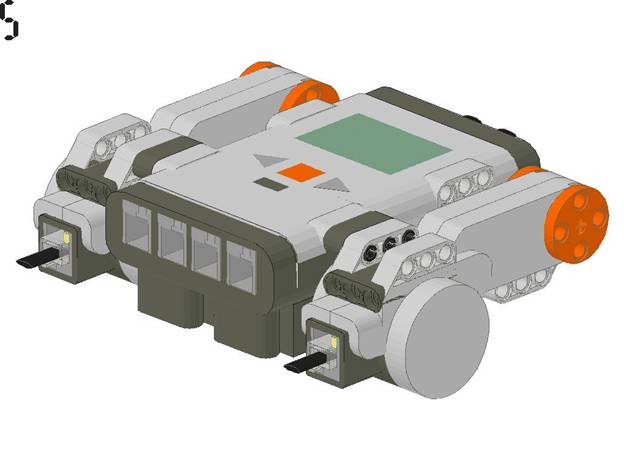
Now you should have a completed project as shown below.
