Difference between revisions of "Sensors"
| Line 103: | Line 103: | ||
<li>To use the rotation sensor to control the speed of the motor, we will use the | <li>To use the rotation sensor to control the speed of the motor, we will use the | ||
Rotation Sensor Block to read the value of the Rotation Sensor on Port B. | Rotation Sensor Block to read the value of the Rotation Sensor on Port B.<br> | ||
[[Image:Lab_sensors_1.jpg]]</li> | [[Image:Lab_sensors_1.jpg]]</li> | ||
<p> </p> | <p> </p> | ||
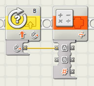
<li>Next we will have to convert the value of the Rotation Sensor to a number value | <li>Next we will have to convert the value of the Rotation Sensor to a number value | ||
that the motor can use to determine speed. We will use the Math Block. | that the motor can use to determine speed. We will use the Math Block.<br> | ||
[[Image:Lab_sensors_2.jpg]]</li> | [[Image:Lab_sensors_2.jpg]]</li> | ||
<p> </p> | <p> </p> | ||
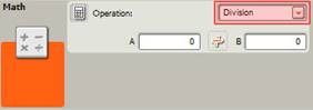
<li>Change the block to Division. You can alter the settings of a block in the | <li>Change the block to Division. You can alter the settings of a block in the | ||
Configuration Panel located in the bottom left corner of the window. | Configuration Panel located in the bottom left corner of the window.<br> | ||
[[Image:Lab_sensors_3.jpg]]</li> | [[Image:Lab_sensors_3.jpg]]</li> | ||
<p> </p> | <p> </p> | ||
| Line 119: | Line 119: | ||
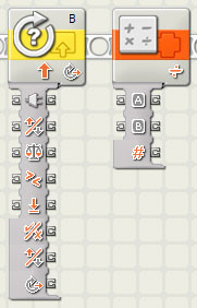
<li>To take the value of the Rotation Sensor, use the drop down menu of the | <li>To take the value of the Rotation Sensor, use the drop down menu of the | ||
Rotation Sensor block. Also do this for the Math Block.</li> | Rotation Sensor block. Also do this for the Math Block.</li> | ||
<p> </p> | |||
<li>Next, highlight the degrees on the Rotation Sensor Block and wire it to “A�? on | <li>Next, highlight the degrees on the Rotation Sensor Block and wire it to “A�? on | ||
| Line 129: | Line 130: | ||
We would ideally like to use 1.8 (i.e Divide by 180 degrees, then Multiply by | We would ideally like to use 1.8 (i.e Divide by 180 degrees, then Multiply by | ||
100%), but MindStorms 1.1 can only recognize whole numbers, not decimals.</li> | 100%), but MindStorms 1.1 can only recognize whole numbers, not decimals.</li> | ||
<p> </p> | |||
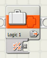
<li>Since we will be using this value further along in the program, we want to store | <li>Since we will be using this value further along in the program, we want to store | ||
this value as a variable. Use a Variable Block and string it next to the Math Bock. | this value as a variable. Use a Variable Block and string it next to the Math Bock.<br> | ||
[[Image:Lab_sensors_6.jpg]]</li> | [[Image:Lab_sensors_6.jpg]]</li> | ||
<p> </p> | <p> </p> | ||
| Line 137: | Line 139: | ||
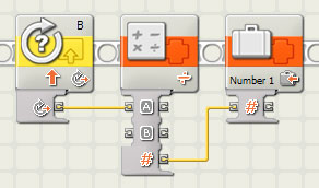
<li>Change the Variable Block settings to “Write�? and “Number 1�?. Using the drop | <li>Change the Variable Block settings to “Write�? and “Number 1�?. Using the drop | ||
down menu in the Variable Block, wire the “#�? output from the Math Block to the | down menu in the Variable Block, wire the “#�? output from the Math Block to the | ||
“#�? input on the Variable Block. The string of code should look like this: | “#�? input on the Variable Block. The string of code should look like this:<br> | ||
[[Image:Lab_sensors_7.jpg]]</li> | [[Image:Lab_sensors_7.jpg]]</li> | ||
<p> </p> | <p> </p> | ||
| Line 144: | Line 146: | ||
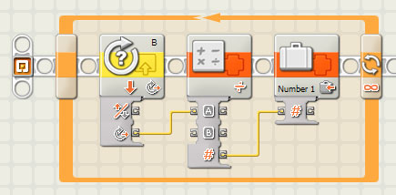
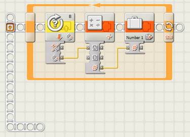
the speed accordingly. To do this we want to use a Loop. Bring out a Loop, | the speed accordingly. To do this we want to use a Loop. Bring out a Loop, | ||
select all the code that was written and place it inside the loop. The final | select all the code that was written and place it inside the loop. The final | ||
line of code should look like this:[[Image:Lab_sensors_8.jpg]]</li> | line of code should look like this:<br> | ||
[[Image:Lab_sensors_8.jpg]]</li> | |||
<h4>TASK 2: USE VARIABLE</h4> | <h4>TASK 2: USE VARIABLE</h4> | ||
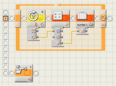
| Line 151: | Line 154: | ||
create another task line hold the “Shift Key�? and click and drag the beam from | create another task line hold the “Shift Key�? and click and drag the beam from | ||
the existing white beam on the left side of the screen. Double click, to confirm | the existing white beam on the left side of the screen. Double click, to confirm | ||
the length and location of the new beam.[[Image:Lab_sensors_9.jpg]]</li> | the length and location of the new beam.<br> | ||
[[Image:Lab_sensors_9.jpg]]</li> | |||
<p> </p> | <p> </p> | ||
| Line 157: | Line 161: | ||
<li>We want our program to start when the Touch Sensor on Port 2 is bumped. | <li>We want our program to start when the Touch Sensor on Port 2 is bumped. | ||
Use a Wait Block.[[Image:Lab_sensors_10.jpg]]</li> | Use a Wait Block.<br> | ||
[[Image:Lab_sensors_10.jpg]]</li> | |||
<p> </p> | <p> </p> | ||
| Line 166: | Line 171: | ||
on Port A, we must account for both direction and speed of the motor. We will | on Port A, we must account for both direction and speed of the motor. We will | ||
use another Variable block to determine direction. Place this after the Wait | use another Variable block to determine direction. Place this after the Wait | ||
for touch block.[[Image:Lab_sensors_11.jpg]]</li> | for touch block.<br> | ||
[[Image:Lab_sensors_11.jpg]]</li> | |||
<p> </p> | <p> </p> | ||
| Line 196: | Line 202: | ||
<h4>TASK 3: MOTOR FLIP DIRECTION</h4> | <h4>TASK 3: MOTOR FLIP DIRECTION</h4> | ||
< | <li>The next task we want to accomplish is to be able to switch the direction | ||
of Motor A if the Touch Sensor on Port 1 is pressed. First, create a new task | of Motor A if the Touch Sensor on Port 1 is pressed. First, create a new task | ||
line as described in Task 2. | line as described in Task 2.</li> | ||
< | <li><img src="lab7_files/image021.jpg">15. Since we want the program to | ||
differentiate between when the Touch Sensor is pressed from when it is not | differentiate between when the Touch Sensor is pressed from when it is not | ||
pressed, we will use a Switch Block. < | pressed, we will use a Switch Block.<br> | ||
[[Image:Lab_sensors_15.jpg]]</li> | |||
<p> </p> | <p> </p> | ||
< | <li>Place the Switch Block on the new task line. Its default is set to Touch | ||
Sensor.</li> | |||
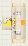
< | <li>The Top and Bottom sections of the Switch Block correspond to whether the | ||
Touch Sensor is pressed or not pressed, respectively. Since we want nothing to | Touch Sensor is pressed or not pressed, respectively. Since we want nothing to | ||
happen when the Touch Sensor is not pressed, leave the Bottom section empty. | happen when the Touch Sensor is not pressed, leave the Bottom section empty. | ||
</ | </li> | ||
< | <li>In the Top Section, we will first place a Variable Block set to Logic 1 | ||
and “Read�?. This will read the value from the Variable Logic Block we created in | and “Read�?. This will read the value from the Variable Logic Block we created in | ||
Step 10. </ | Step 10.</li> | ||
<li>Since the direction of the Motor corresponds to the True or False value stated | |||
in the Variable Logic Block from Task 2, it is then possible to use a Logic Block | |||
to change its value.<br> | |||
[[Image:Lab_sensors_16.jpg]]</li> | |||
<p> </p> | <p> </p> | ||
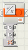
< | <li>The Logic Block allows you to use operations such as AND, OR & NOT in the | ||
Configuration Panel in the lower left corner of the window. Now place a Logic | Configuration Panel in the lower left corner of the window. Now place a Logic | ||
Block set to “NOT�? in the code string. </ | Block set to “NOT�? in the code string. </li> | ||
< | <li>To change the value of the Variable Logic Block from its value of True to | ||
False, wire the “Value�? of the Variable Logic Block to “A�? in the drop down menu | False, wire the “Value�? of the Variable Logic Block to “A�? in the drop down menu | ||
of the Logic Block. Next we want to place another Variable Block set to Logic 1 | of the Logic Block. Next we want to place another Variable Block set to Logic 1 | ||
| Line 252: | Line 240: | ||
Variable Logic Block via the drop down menus. We are basically saying that if | Variable Logic Block via the drop down menus. We are basically saying that if | ||
the Value of Logic 1 is TRUE, then “NOT TRUE�? gives a result of FALSE. Your | the Value of Logic 1 is TRUE, then “NOT TRUE�? gives a result of FALSE. Your | ||
code should look like this: </ | code should look like this: </li> | ||
<p> | <p>[[Image:Lab_sensors_17.jpg]]</p> | ||
<li>Next we want to place a Wait Block changed to Time.<br> | |||
[[Image:Lab_sensors_18.jpg]]</li> | |||
<p> </p> | <p> </p> | ||
< | <li>Have it Wait for 1 second.</li> | ||
< | <li>Lastly, we want to constantly check if the touch sensor is being pressed, so | ||
place the entire Switch Block within a Loop Block. The Wait Block is necessary | place the entire Switch Block within a Loop Block. The Wait Block is necessary | ||
due to the fact that when the Touch Sensor is pressed we want the program to | due to the fact that when the Touch Sensor is pressed we want the program to | ||
Wait a certain amount of time so the Motor can change direction before the Loop | Wait a certain amount of time so the Motor can change direction before the Loop | ||
rechecks its direction. Your final code for this task should look like: </ | rechecks its direction. Your final code for this task should look like:</li> | ||
<p> | <p>[[Image:Lab_sensors_19.jpg]]</p> | ||
< | <h4>TASK 4: STOP MOTOR A AFTER TOUCH SENSOR 2 IS PRESSED</h4> | ||
< | <li>The last task simply ends the program when Touch Senor 2 is pressed. | ||
First, create a new task string.</ | First, create a new task string.</li> | ||
< | <li>Place 2 Wait Blocks in sequence. Set them to Touch Sensor and “Bumped.�? The | ||
first Wait Block is to account for the Start of the program, as indicated in | |||
Step 9. The second Wait Block will be used to determine when to end the program. | Step 9. The second Wait Block will be used to determine when to end the program. | ||
</ | </li> | ||
<li>Next, place a Stop Block.<br> | |||
[[Image:Lab_sensors_20.jpg]]</li> | |||
<p> </p> | <p> </p> | ||
<p>This Block will stop the whole program.</p> | <p>This Block will stop the whole program.</p> | ||
< | <li>Your final code for this task should look like:</li> | ||
<p> | <p>[[Image:Lab_sensors_21.jpg]]</p> | ||
<p>If you followed each step correctly, your Final Code for Part A should | <p>If you followed each step correctly, your Final Code for Part A should | ||
resemble: </p> | resemble: </p> | ||
<p> | <p>[[Image:Lab_sensors_22.jpg]]</p> | ||
< | <li>Test your Program. After a TA approves that it works correctly, Save it and | ||
move onto Part B. </ | move onto Part B.</li> | ||
</ol> | |||
<h3>Part B:</h3> | <h3>Part B:</h3> | ||
<p>In this part of the program you will modify what you had created in Part A to | <p>In this part of the program you will modify what you had created in Part A to | ||
include the ultrasonic sensor. | include the ultrasonic sensor. In this portion of the exercise you will to | ||
add another task to utilize the ultrasonic sensor connected to Port 3. | add another task to utilize the ultrasonic sensor connected to Port 3. In | ||
addition to its functionality from Part A, the motor must now reverse itself | addition to its functionality from Part A, the motor must now reverse itself | ||
when the ultrasonic sensor on Port 3 detects a distance greater than 20cm or | when the ultrasonic sensor on Port 3 detects a distance greater than 20cm or | ||
less than 8cm. | less than 8cm. The idea behind this is to keep the motor on the track at | ||
all times. | all times. Using what you have learned in Part A you can create this | ||
portion of the program on your own. | portion of the program on your own. Remember to save your VI. Once | ||
you are done, you may move on to Part C.</p> | you are done, you may move on to Part C.</p> | ||
| Line 322: | Line 302: | ||
<p>In this part of the program you will modify what you have done in Parts A and | <p>In this part of the program you will modify what you have done in Parts A and | ||
B. | B.You will add the light sensor to Port 4 and use input from that to stop | ||
the motor. | the motor. When the light sensor connected to Port 4 detects the red ball, | ||
the motor will stop. | the motor will stop. You will need to determine what the light sensor | ||
value for the color red is. To do this, maneuver the red ball near the light | value for the color red is. To do this, maneuver the red ball near the light | ||
sensor. | sensor.On the NXT module, go to the View menu, Reflected Light, and choose | ||
Port 4. | Port 4.The percentage value displayed on the NXT module is the light | ||
sensor value for red. Use this to finish this final part of the program.</p> | sensor value for red. Use this to finish this final part of the program.</p> | ||
<p>When this program is done the touch sensor on Port 1 should be able to | <p>When this program is done the touch sensor on Port 1 should be able to | ||
start Motor A and also flip its direction. | start Motor A and also flip its direction.The touch sensor on Port 2 | ||
should be able to stop Motor A and end the program. | should be able to stop Motor A and end the program. The ultrasonic sensor | ||
on Port 3 should be able to reverse the direction of the motor when the distance | on Port 3 should be able to reverse the direction of the motor when the distance | ||
of the motor is greater than 20cm or less than 8cm from the wall. | of the motor is greater than 20cm or less than 8cm from the wall. And the | ||
light sensor on Port 4 should be able to stop Motor A and end the program when | light sensor on Port 4 should be able to stop Motor A and end the program when | ||
it sees the red ball. | it sees the red ball. Also, the speed of Motor A is controlled by Motor | ||
B.</p> | B.</p> | ||
<p | <p>[[Image:Lab_sensors_23.jpg]]</p> | ||
<p align=center>Figure 1: Test Assembly, angled view</p> | <p align=center>Figure 1: Test Assembly, angled view</p> | ||
<p | <p>[[Image:Lab_sensors_24.jpg]]</p> | ||
<p align=center>Figure 2: Test Assembly, side view</p> | <p align=center>Figure 2: Test Assembly, side view</p> | ||
<p | <p>[[Image:Lab_sensors_25.jpg]]</p> | ||
<p align=center>Figure 3: Test Assembly, top view</p> | <p align=center>Figure 3: Test Assembly, top view</p> | ||
<h4>Testing</h4> | <h4>Testing</h4> | ||
<p>In order to test your program, ask your TA for the assembly, connect the | <p>In order to test your program, ask your TA for the assembly, connect the | ||
NXT to the USB outlet and run the program you created.</p> | NXT to the USB outlet and run the program you created.</p> | ||
<h4>Wait </h4> | <h4>Wait</h4> | ||
<p>[[Image:Lab_sensors_26.jpg]][[Image:Lab_sensors_27.jpg]] | |||
[[Image:Lab_sensors_28.jpg]][[Image:Lab_sensors_29.jpg]] | |||
[[Image:Lab_sensors_30.jpg]]</p> | |||
<p>The Wait Block allows your program to wait (pause) for a certain amount of | <p>The Wait Block allows your program to wait (pause) for a certain amount of | ||
time, or until a particular condition is met. The program will run up to the | time, or until a particular condition is met. The program will run up to the | ||
| Line 365: | Line 347: | ||
the specific condition has been met. If a Wait command needs information from a | the specific condition has been met. If a Wait command needs information from a | ||
sensor, the sensor in the Configuration Panel of the block located in the bottom | sensor, the sensor in the Configuration Panel of the block located in the bottom | ||
left corner of the screen. This is so Mindstorms knows where to find it. | left corner of the screen. This is so Mindstorms knows where to find it.</p> | ||
<h4>Switch</h4> | <h4>Switch</h4> | ||
< | |||
<p>[[Image:Lab_sensors_31.jpg]]</p> | |||
<p>The Switch Block command is in the Flow menu. It will split the path of the | <p>The Switch Block command is in the Flow menu. It will split the path of the | ||
| Line 380: | Line 359: | ||
for sensor input.</p> | for sensor input.</p> | ||
<h4>Task Split</h4> | <h4>Task Split</h4> | ||
<p> | <p>[[Image:Lab_sensors_32.jpg]]</p> | ||
<p>To create two independent tasks that run simultaneously, you must create a | <p>To create two independent tasks that run simultaneously, you must create a | ||
| Line 395: | Line 370: | ||
<h4>Loops</h4> | <h4>Loops</h4> | ||
<p> | |||
<p>[[Image:Lab_sensors_33.jpg]]</p> | |||
<p>The Loop block is under the Flow menu. You can set the loop to constantly | <p>The Loop block is under the Flow menu. You can set the loop to constantly | ||
| Line 403: | Line 379: | ||
of it until the program ends. </p> | of it until the program ends. </p> | ||
< | <h4>Touch Sensors</h4> | ||
<p>There are touch sensor blocks that use the Wait, Loop, and Switch | <p>There are touch sensor blocks that use the Wait, Loop, and Switch | ||
structures.</p> | structures.</p> | ||
<p> | <p>[[Image:Lab_sensors_34.jpg]][[Image:Lab_sensors_35.jpg]][[Image:Lab_sensors_30.jpg]]</p> | ||
<p>The touch sensor Wait Block commands will pause the motor(s) until the | <p>The touch sensor Wait Block commands will pause the motor(s) until the | ||
| Line 437: | Line 399: | ||
<h4>Light Sensors</h4> | <h4>Light Sensors</h4> | ||
<p>There are light sensor blocks that use the Wait, Loop, and Switch | <p>There are light sensor blocks that use the Wait, Loop, and Switch | ||
structures.</p> | structures.</p> | ||
Revision as of 02:32, 12 October 2007
EG1004 Lab 7: Sensors
1 OBJECTIVES
The experimental objective of this lab is to design two programs. The first is a Mindstorms program that uses light, touch and ultrasonic sensors to stop a motor when a red ball is detected. The second is a LabVIEW program that uses a thermocouple to measure air temperature in the heating and cooling program you designed in the LabVIEW Lab.
We will learn to use light, touch, ultrasonic and rotation sensors so that we can use these tools in our semester-long design projects.
2 OVERVIEW
Mindstorms Program
Before we can learn to use sensors, we must become familiar with the NXT. Remember that the Mindstorms program is a compiler: a program used to make other programs. Just as a compiler is used when creating and debugging a C++ program, Mindstorms similarly compiles programs for the NXT. The Mindstorms interface is graphic; a text compiler like those used for C++ is not. However, the principle is very much the same. Actions are taken based upon circumstances set by the programmer.
The NXT houses all the programming instructions that control the movement of your robot. Once you have created your program in Mindstorms, it is uploaded to the NXT. The NXT then dictates the robot's motion. If your robot does not do what you intended, you must rewrite the program in Mindstorms and upload the corrected version to the NXT.
LabVIEW Program
The thermocouple records temperatures that are transmitted through the DAC board. LabVIEW uses these values to operate the heating and cooling system you designed in the LabVIEW Lab. To program your heating and cooling system VI to gather information from an outside source (thermocouple), you must add an AI Sample Channel. In order to wire this VI, you must right-click on the icon, select Visible Items, and then Terminals.
Developing advanced programming skills in both Mindstorms and LabVIEW will allow you to successfully complete your semester-long design project. This lab will help you acquire those skills.
3 YOUR ASSIGNMENT
- A Zip file including all LabVIEW programs (.vi) needs to be submitted to the EG1004 Web site. If you don't know how to make a zip file, read the page How to Compress Your Files in the Instructional Presentations section of this manual.
Lab Report
There is no lab report for this lab.
Team PowerPoint Presentation
There is no presentation for this lab.
4 MATERIALS AND EQUIPMENT
- Lab PC
- Mindstorms and LabVIEW Software
- USB Cable
- NXT Unit
- Multiple NXT Sensor Array
- DAC Board
- Thermocouple
5 PROCEDURE
Program 1: Mindstorms Sensors
The program is broken up into three main parts. In Part A you will use the touch sensors to start, stop and reverse the direction of the motor. In Part B you will add the ultrasonic sensor to the program and have it reverse the direction of the motor when it is greater than 20cm or less than 8cm from the wall. In Part C you will add the light sensor to the program in order to stop the motor when it detects a red ball. Your TA will provide you with access to a testing assembly. You can see pictures of the testing assembly in Figures 1-3. Remember to test after each part.
Part A:
In this part of the exercise you first create a program that causes Motor A to move when the touch sensor connected to Port 1 is pushed and stop when the touch sensor connected to Port 2 is pushed. Also if the touch sensor connected to Port 1 is pushed while the motor is running then the motor must flip direction. There is a motor connected to Port B, and this motor will control the speed of Motor A, using the motor’s rotation sensor. The following steps will help you build part of this program.
TASK 1: STORE VARIABLE
- Open MindStorms 1.1. Create a new program.
- To use the rotation sensor to control the speed of the motor, we will use the
Rotation Sensor Block to read the value of the Rotation Sensor on Port B.

- Next we will have to convert the value of the Rotation Sensor to a number value
that the motor can use to determine speed. We will use the Math Block.

- Change the block to Division. You can alter the settings of a block in the
Configuration Panel located in the bottom left corner of the window.
- To take the value of the Rotation Sensor, use the drop down menu of the Rotation Sensor block. Also do this for the Math Block.
- Next, highlight the degrees on the Rotation Sensor Block and wire it to “A�? on
the Math Block.
This takes the value of the Rotation Sensor and uses that as input A on the Math Block. - In the Math Block type “2�? into the “B�? box. This will convert the degrees of the Rotation Sensor to a percentage that the motor value can read. We would ideally like to use 1.8 (i.e Divide by 180 degrees, then Multiply by 100%), but MindStorms 1.1 can only recognize whole numbers, not decimals.
- Since we will be using this value further along in the program, we want to store
this value as a variable. Use a Variable Block and string it next to the Math Bock.
- Change the Variable Block settings to “Write�? and “Number 1�?. Using the drop
down menu in the Variable Block, wire the “#�? output from the Math Block to the
“#�? input on the Variable Block. The string of code should look like this:
- We want to constantly check the value of the Rotation Sensor and change
the speed accordingly. To do this we want to use a Loop. Bring out a Loop,
select all the code that was written and place it inside the loop. The final
line of code should look like this:
- In a separate task we want to write the code to start our program. To
create another task line hold the “Shift Key�? and click and drag the beam from
the existing white beam on the left side of the screen. Double click, to confirm
the length and location of the new beam.
- Create a new line under the first line of code written.
- We want our program to start when the Touch Sensor on Port 2 is bumped.
Use a Wait Block.
- Its default is a Wait For Touch. Change the settings accordingly to Port 2 and Bumped.
- Next, we want to use the stored Variable. Since we will be using the Motor
on Port A, we must account for both direction and speed of the motor. We will
use another Variable block to determine direction. Place this after the Wait
for touch block.
- This will be set to Logic 1 and “Write�?. Logic dictates that True will be Forward and False will be Reverse. The Logic Variable Block must be set to True in order for the motor to go forward when the program starts.
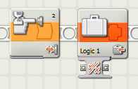
- Now we want to use the Stored Variable in conjunction with a Variable Logic Block to control the Motor A. Place another Variable block set to Number 1 and�? Read�?. This will read the value from the Stored Variable 1. Then place a Variable Block set to Logic 1 and “Read�?. This will read the value from the previous Variable Logic Block. Lastly place a Motor A Block. Your task so far should look like this:
- Wire the Variable and Logic Blocks to Motor A using their respective drop down menus. Remember, you want to control Direction and Power of Motor A.
- Finally, you want to constantly control the speed of Motor A. Insert a Loop into the string of code and place inside of it the two Variable Blocks and the Motor A block. Your final code for this task should look like this:
- The next task we want to accomplish is to be able to switch the direction of Motor A if the Touch Sensor on Port 1 is pressed. First, create a new task line as described in Task 2.
- <img src="lab7_files/image021.jpg">15. Since we want the program to
differentiate between when the Touch Sensor is pressed from when it is not
pressed, we will use a Switch Block.
- Place the Switch Block on the new task line. Its default is set to Touch Sensor.
- The Top and Bottom sections of the Switch Block correspond to whether the Touch Sensor is pressed or not pressed, respectively. Since we want nothing to happen when the Touch Sensor is not pressed, leave the Bottom section empty.
- In the Top Section, we will first place a Variable Block set to Logic 1 and “Read�?. This will read the value from the Variable Logic Block we created in Step 10.
- Since the direction of the Motor corresponds to the True or False value stated
in the Variable Logic Block from Task 2, it is then possible to use a Logic Block
to change its value.
- The Logic Block allows you to use operations such as AND, OR & NOT in the Configuration Panel in the lower left corner of the window. Now place a Logic Block set to “NOT�? in the code string.
- To change the value of the Variable Logic Block from its value of True to False, wire the “Value�? of the Variable Logic Block to “A�? in the drop down menu of the Logic Block. Next we want to place another Variable Block set to Logic 1 and “Write�?. Now wire the “Result�? of the Logic Block to the�? Value�? of this Variable Logic Block via the drop down menus. We are basically saying that if the Value of Logic 1 is TRUE, then “NOT TRUE�? gives a result of FALSE. Your code should look like this:
- Next we want to place a Wait Block changed to Time.

- Have it Wait for 1 second.
- Lastly, we want to constantly check if the touch sensor is being pressed, so place the entire Switch Block within a Loop Block. The Wait Block is necessary due to the fact that when the Touch Sensor is pressed we want the program to Wait a certain amount of time so the Motor can change direction before the Loop rechecks its direction. Your final code for this task should look like:
- The last task simply ends the program when Touch Senor 2 is pressed. First, create a new task string.
- Place 2 Wait Blocks in sequence. Set them to Touch Sensor and “Bumped.�? The first Wait Block is to account for the Start of the program, as indicated in Step 9. The second Wait Block will be used to determine when to end the program.
- Next, place a Stop Block.

- Your final code for this task should look like:
- Test your Program. After a TA approves that it works correctly, Save it and move onto Part B.


TASK 2: USE VARIABLE


TASK 3: MOTOR FLIP DIRECTION


TASK 4: STOP MOTOR A AFTER TOUCH SENSOR 2 IS PRESSED

This Block will stop the whole program.

If you followed each step correctly, your Final Code for Part A should resemble:

Part B:
In this part of the program you will modify what you had created in Part A to include the ultrasonic sensor. In this portion of the exercise you will to add another task to utilize the ultrasonic sensor connected to Port 3. In addition to its functionality from Part A, the motor must now reverse itself when the ultrasonic sensor on Port 3 detects a distance greater than 20cm or less than 8cm. The idea behind this is to keep the motor on the track at all times. Using what you have learned in Part A you can create this portion of the program on your own. Remember to save your VI. Once you are done, you may move on to Part C.
Part C:
In this part of the program you will modify what you have done in Parts A and B.You will add the light sensor to Port 4 and use input from that to stop the motor. When the light sensor connected to Port 4 detects the red ball, the motor will stop. You will need to determine what the light sensor value for the color red is. To do this, maneuver the red ball near the light sensor.On the NXT module, go to the View menu, Reflected Light, and choose Port 4.The percentage value displayed on the NXT module is the light sensor value for red. Use this to finish this final part of the program.
When this program is done the touch sensor on Port 1 should be able to start Motor A and also flip its direction.The touch sensor on Port 2 should be able to stop Motor A and end the program. The ultrasonic sensor on Port 3 should be able to reverse the direction of the motor when the distance of the motor is greater than 20cm or less than 8cm from the wall. And the light sensor on Port 4 should be able to stop Motor A and end the program when it sees the red ball. Also, the speed of Motor A is controlled by Motor B.

Figure 1: Test Assembly, angled view

Figure 2: Test Assembly, side view

Figure 3: Test Assembly, top view
Testing
In order to test your program, ask your TA for the assembly, connect the NXT to the USB outlet and run the program you created.
Wait


The Wait Block allows your program to wait (pause) for a certain amount of time, or until a particular condition is met. The program will run up to the Wait command and then pause until the set period of time has elapsed or until the specific condition has been met. If a Wait command needs information from a sensor, the sensor in the Configuration Panel of the block located in the bottom left corner of the screen. This is so Mindstorms knows where to find it.
Switch

The Switch Block command is in the Flow menu. It will split the path of the program based on a condition you set. For instance, the program will perform one of two tasks depending on the value it receives from a sensor. Sensor switches must be specified in the Configuration Panel so Mindstorms knows where to look for sensor input.
Task Split

To create two independent tasks that run simultaneously, you must create a new beam to place blocks on. As illustrated, begin on left side of the screen where the first line of code is written. Hold the “Shift�? key and your “pointer�? will change to a spool of “wire.�? Drag the spool to your desired destination and double click to confirm the new beam.
Loops

The Loop block is under the Flow menu. You can set the loop to constantly check for certain conditions based on what criteria is selected in the Configuration Panel. Loops can depend on Time, Count, Sensor or Logic Values. Loops can also be set to “Forever.�? This will continue to Loop the code inside of it until the program ends.
Touch Sensors
There are touch sensor blocks that use the Wait, Loop, and Switch structures.


The touch sensor Wait Block commands will pause the motor(s) until the touch sensor is pressed, released or bumped, depending on its configuration.
The touch sensor Loop executes until the sensor is pressed, released or bumped, depending on its configuration.
The touch sensor Switch takes one input and produces two outputs, splitting the path into two possibilities. The first possibility is the result when the touch sensor is pushed and the second is the result when the touch sensor is released.
Light Sensors
There are light sensor blocks that use the Wait, Loop, and Switch structures.
<img src="lab7_files/image049.jpg"><img src="lab7_files/image050.jpg"><img src="lab7_files/image039.jpg">
The light sensor Wait Block will pause the motor(s) when the measured value of reflected light is greater than or less than a constant value, depending on its configuration.
The light sensor Loop executes until the measured value of reflected light is greater than or less than a constant value, depending on its configuration.
The light sensor Switch takes one input and produces two outputs, splitting the path into two possibilities. The first possibility is the result when the value of reflected light is greater than a constant value and the second is the result when the value is less than the constant.
Ultrasonic Sensors
<img src="lab7_files/image051.jpg">There are ultrasonic sensor blocks that use the Wait, Loop, and Switch structures.
<img src="lab7_files/image052.jpg"><img src="lab7_files/image041.jpg">
The ultrasonic sensor Wait Block will pause the motor(s) when the distance measured is greater than or less than a constant value, depending on its configuration.
The ultrasonic sensor Loop executes until the distance measured is greater than or less than a constant value, depending on its configuration.
The ultrasonic sensor Switch takes one input and produces two outputs, splitting the path into two possibilities. The first possibility is the result when the distance measured is greater than the constant value and the second is the result when the value is less than the constant.
Timers
There are Timer blocks that use the Wait, Loop, and Switch structures.
Timer structures are linked and used like the sensors are used; however, instead of getting values from sensors, they hold values in timer containers. Timers count the time elapsed from when they are reset.
<img src="lab7_files/image053.jpg"><img src="lab7_files/image054.jpg"><img src="lab7_files/image042.jpg">
The Timer Wait Block will pause the program as it waits for the timer value to match the input value.
The Timer Loop executes a selection of code while the timer is less than or greater than a certain value.
The Timer Switch works the same as the light, touch and ultrasonic sensor switches. It compares the value of the timer to a set value and pauses the program until the timer equals the value it is being compared to.
Variables
Variables can be used to store Number, Logic or Text Values. Variables can “Written�? (1) or “Read�? (2).
<img src="lab7_files/image055.jpg"><img src="lab7_files/image056.jpg">
(1) (2)
In order to use variables correctly you should first define a variable by either “writing�? it or by storing an input value from a sensor. You can then use the Variable by “reading�? it. Both methods are used in Part A of this lab.
Program 2: LabVIEW Temperature Indicator System
- Open the heating and cooling program you designed in the LabVIEW Lab . Switch the case to the automatic case.
- From the Functions palette select All Functions, NI measurements, and Data Acquisition, then select Analog Input, and then AI Sample Channel.
- Drag and drop the AI Sample Channel node into the automatic case on the back panel of your existing program.
- Right-click on the AI Sample Channel node and select Visible Items, then Terminals.
- Right-click on the AI Sample Channel node and click the Select Type menu. Select Scaled Value.
- Wire the AI Sample Channel node as shown in Figure 4.
<img src="lab7_files/image058.jpg">
Figure 4: AI Sample Channel node
Wiring the Sample Channel node
- Device ID (integer): the DAC board is recognized by the computer as 1.
- Channel (string): for our purposes we will always set this to thermocouple .
- Upper Limit (real number): for our purposes we will always set this to +5.
- Lower Limit (real number): for our purposes we will always set this to -5.
- Output.
- Change the thermometer to an Indicator by right clicking on it and selecting Change to Indicator.
- Connect the output from the Sample Channel to the thermometer.
Testing Your Design
- Connect the yellow wire of the thermocouple to pin 3 on the DAC board.
- Connect the orange wire of the thermocouple to pin 4 on the DAC board.
- Run the program continuously.
- Hold the thermocouple between your fingers to make the temperature rise. Confirm that the indicator on your program rises.
- Place thermocouple in a cup of cold water to make the temperature fall. Confirm that the indicator on your program falls.
Have all sketches and original data signed by your TA. Your lab work is now complete.
Please clean up your workstation. Return all unused materials to your TA.
Refer to section 3 Your Assignment for the instructions you need to prepare your assignments this week.
</html>