Introduction to LabVIEW
1 OBJECTIVES
The experimental objective of this lab is to design three systems using LabVIEW:
- A digital calculator
- A lighting system for a building
- A thermal control system that automatically turns on heating and cooling equipment
Building these systems allows us to investigate the potential for using simulated instruments in the laboratory. These programs will let you to obtain data from outside the computer and incorporate it into your program design. In contrast to the more common text-based languages, LabVIEW uses a graphical programming language. You will learn the logic of graphical programming during the course of this lab.
2 OVERVIEW
Adapted from Introduction to LabVIEW, Six-Hour Course.1
LabVIEW is a development environment for creating graphical programs, called virtual instruments (VIs), to simulate actual laboratory instruments. A VI consists of two parts: a front panel and a back panel. The front panel allows the user to interact with the VI by displaying output and allowing the user to supply the program with input. The back panel consists of the actual code used by the VI to obtain input from the front panel, operate on the input, and display the results.
The front panel is built using controls and indicators. Controls are inputs – they allow a user to supply information to the VI. Indicators are outputs – they indicate, or display, the results based on the inputs given to the VI. Controls consist of switches, knobs, dials, buttons, etc. and indicators consist of meters, gauges, LEDs, displays, etc. These are located on the Controls palette and can be placed on the front panel.
The back panel, which is a block diagram, contains the graphical source code. All of the objects placed on the front panel will appear on the back panel as terminals. The back panel also contains structures and functions which perform operations on controls and supply data to indicators. The structures and functions are found on the Functions palette and can be placed on the back panel. Collectively controls, indicators, structures and functions will be referred to as nodes. Nodes are connected to one another using wires – e.g. two controls and an indicator can be wired to the addition function so that the indicator displays the sum of the two controls.
In any programming language, structures allow you to create conditions. In LabVIEW you can access structures by opening the Functions palette and selecting Structures. The following are some examples of structures:
- The While Loop is similar to do loop or while in text-based programming languages. It executes its subdiagram (or subroutine) until it receives a false value.
- The For Loop executes a subdiagram a set number of times, specified by the value in the count terminal.
- The Case Structure is similar to if/else, switch/case or match/with in text-based programming languages. It contains multiple subdiagrams – one for each possible value of the input to the case structure (the control wired to the '?').
The data acquisition and control (DAC) board is LabVIEW's physical interface with the outside world. Keep in mind that National Instruments offers different hardware solutions to meet their clients' individual needs. Using the available hardware, the only digital output port available is Port 0. Keep this in mind as this will be important when setting up the DAQ Assistant.
Some useful key shortcuts to keep in mind when working in the LabVIEW environment:
- CTRL+H: Show/hide context help.
- CTRL+B: Clean up broken wiring.
- CTRL+E: Toggle between front/back panels.
- CTRL+Z: Undo last action.
3 YOUR ASSIGNMENT
Individual Lab Report
A Zip file including all LabVIEW programs (.vi) needs to be submitted to the EG Website. If you don't know how to make a zip file, read the page How to Compress Your Files in the Instructional Presentations section.
Follow the lab report guidelines laid out in the page called Specifications for Writing Your Lab Reports in the Technical Communication section of this manual. As you write, the following discussion points should be addressed in the appropriate section of your lab report:
- Explain what LabVIEW is and describe how it helps engineers and scientists with their work.
- Explain what a VI is.
- What are controls and indicators?
- What are structures and functions?
- What is the Front Panel used for? The Back Panel?
- Discuss what a DAC board is.
- Were the objectives of the experiment achieved? If not why?
- Describe the advantages and disadvantages of using LabVIEW.
- Suggest some improvements of how the lab could have be conducted better.
IMPORTANT: Because the procedural elements in this lab are extensive, please include only the procedures you employed to build Design 2, the Heating and Cooling System in your lab report. You do not need to document the procedures you followed to build Design 1: the Simple Calculator, or Design 3: Lighting System.
Note: You still need to include ALL the designs in the other sections of your lab report.
Remember, your job in this lab is not to report whether the Heating and Cooling system worked. Your job is to report on what you did to design it. Please consider the value of LabVIEW as a substitute for actual instruments and systems. Your Data/Observations section should include information on ease of use, the LabVIEW user interface, and the help options available to you.
In describing the design of all the systems, you should show screen shots in your lab reports showing the Virtual Instruments you designed. If you don't know how to take a screen shot and include it in your report, look at the Online Manual under "Instructional Web Pages" for instructions on how to take a screen shot and use it.
Team PowerPoint Presentation (Sections HS1 & HS2 Only)
For Sections A, B, C, D, E, F, and G: there is no presentation for Lab 4; Milestone 1 presentations are due.
Follow the presentation guidelines laid out in the page called EG1003 Lab Presentation Format in the Introduction to Technical Presentations section of this manual. When you are preparing your presentation, consider the following points:
- What is the importance of LabVIEW?
- Discuss some ways LabVIEW can be used in industry
4 MATERIALS AND EQUIPMENT
- Lab PC
- LabVIEW Software
- Data acquisition and control (DAC) board
- Breadboard
- Several LEDs
5 PROCEDURE
- Open LabVIEW, select New and Blank VI.
- Click on Window and select Tile Left & Right to set the front panel (left window) and back panel (right window) side by side. This will make them visible at the same time, making it easier to work.
- On the right window, pull down the View menu, select Show Tools Palette.
- On the left window, pull down the Window menu again, select Show Controls Palette. At this point your screen should look like Figure 3. Note the Controls Palette and the Tools Palette, and their icons.

Remember: You are required to take notes. Experimental details are easily forgotten unless written down. EG Standard Note Paper can be downloaded and printed from the EG website the EG Website. Use your lab notes to write the Procedure section of your lab report. At the end of each lab your TA will scan your lab notes and upload them to the Lab Documents section of the EG Website. You must attach your lab notes at the end of your lab report (use the "Insert Object" command in MS Word after your Conclusion). Keeping careful notes is an essential component of all scientific practice.
For help with the operation of any LabVIEW icon, select Help from the main menu bar, choose Show Context Help, and click the icon whose operation you don't understand. It will be explained in the open window.
The overall approach for each of these projects is to place items on the front panel that the user will see and interact with. The corresponding items on the back panel will then actually make the device work, and how you "wire" them together will determine how your device works.
Note: We'll be doing some tasks a number of times, where you'll be clicking on the same icons to bring up various components. To help you , we've included a LabVIEW digest at the end of this lab for your reference to help you navigate.
Design 1: Simple Calculator
Create a program that simulates a basic calculator. Your calculator will be able to add, subtract, and multiply.
- The front panel must contain:
- One slide to control the arithmetic operation to be performed. Here's how to do it:
- Select the Num Ctrls icon
 on the Controls Palette (see Figure 4). This
will bring up the window shown in Figure 5
on the Controls Palette (see Figure 4). This
will bring up the window shown in Figure 5
 Figure 4: Controls Palette
 Figure 5: Numerical Controls window
 - Then select Horizontal Pointer Slide from the icons shown. Click on the left window to place the slide
on the front panel at the location you select.
Note: If you don't like where you put the slide, click on it and hold down the left mouse button to "drag" the control where you want it. When it's at the right place, let go of the left mouse button. This will work for everything you do on both windows (front and back panels).
Note: As you place items on the front panel (left window), symbols corresponding to each item will appear on the back panel (right window). After we complete the front panel, we'll wire the items on the back panel to make the calculator work.
- Click on the number 10
and change it to 2. Now the slide control will look like Figure 6.
 Figure 6: Slide control with range changed from 10 to 2
 - Right click on the slide to bring up a pull down menu. Select Representation,
and choose the I32 icon. Figure 7
shows what the pull down menus look like, and the I32 icon. This completes the
slide control on the front panel.
 Figure 7: I32 Representation pull down menus
- Select the Num Ctrls icon
- Three Boolean indicators to specify the operation selected. Here's how to do it:
- On the Controls palette, select the LEDs icon
 .
This will bring up the window shown in Figure 8.
.
This will bring up the window shown in Figure 8.
 Figure 8: LEDs Window
 - Select the Round LED icon from the icons shown. Click on the left window to place the LED on the front panel at the location youh select. The best place to put it is centered under the slide. Do this two more times, putting the lights on each side of the first light you made, so you have a total of three lights in a row under the slide.
- Rename the three LEDs to correspond to the functions the calculator will be
performing: add, subtract, and multiply. To rename each LED, click on the
Edit Text icon
 on the Tools
palette. Then click on the 'Boolean' label on each LED and replace it with
the proper text: "add" for the left light, "subtract" for the center light, and
"multiply" for the right light.
on the Tools
palette. Then click on the 'Boolean' label on each LED and replace it with
the proper text: "add" for the left light, "subtract" for the center light, and
"multiply" for the right light.
- On the Controls palette, select the LEDs icon
- Two numeric controls to allow the user to input data from the keyboard. Here's how to do it:
- On the Controls palette, click on the Num Ctrls icon. This will bring up the window shown in Figure 5 again.
- Click on the Num Ctrl icon and click on the left window to the left of the slide to place a numeric control there. This will look like a window you can enter data in. Click the Num Ctrl icon again, and place another numeric control on the right side of the slide.
- A numeric indicator to display the output. Here's how to do it:
- On the Controls palette, click on the Num Inds icon
 .
This will bring up the window shown in Figure 9.
.
This will bring up the window shown in Figure 9.
 Figure 9: Num Inds Window
 - Click on the Num Ind icon and click on the left window
centered below the three lights. This numeric indicator will be the answer from
the calculator.
Note: This numeric indicator, used for output, is a different type of object from the two numeric controls (which are for input) that you constructed earlier in Item c.
- You are now finished constructing the front panel. The finished Front Panel should look like Figure 10:
- On the Controls palette, click on the Num Inds icon
 Figure 10: Finished Front Panel
As we stated earlier, on the back panel there are icons corresponding to everything you put on the front panel. We will now arrange them, add additional objects, and connect them together to make the calculator work.
- One slide to control the arithmetic operation to be performed. Here's how to do it:
- The back panel must contain:
- At least one case statement to control the arithmetic operations. This case statement
will be the heart of the calculator. Here's how you do it:
- Drag all the Boolean nodes to the right edge of the window and all numeric controls and
indicator to the bottom of the window. Place the slide node on the left edge of the window.
This will leave a large area in the middle that you will fill in at the next few
steps. Your back panel should now look like Figure 11.
 Figure 11: Rearranged Back Panel
 - In the block diagram (back panel) of LabVIEW, go to the menu bar, select View, and choose "Functions Palette", just as shown on Figure 12a. This will bring up the Functions Palette, shown in Figure 12b.
 Figure 12a: How to bring up the Functions Palette
 Figure 12b: Functions Palette
 - Click on the Exec Ctrl icon
 . This will
bring up the Exec Ctrl window, shown in Figure 13.
. This will
bring up the Exec Ctrl window, shown in Figure 13.
 Figure 13: Exec Ctrl Window
 - Click on the Case Structure icon. Click on the right window to locate it on the back panel. Be careful, it's a very large object, and will have many connections. Your best strategy is to locate it in the middle of the panel. Note that at the top of the object there a caption box with the number 1 in it. On each side of the caption box are arrows pointing to the left and right. Note also the question mark on the left side of the case structure object. This is the input to the case structure.
- We will now start
connecting things. First, we need to access the proper tool. On the Tools
Palette, chose the "Connect Wire" icon
 . We'll now connect
the slide to the case structure. Connect the slide to the case structure by clicking on the slide object, and then on the
question mark on the left side of the case structure. Your back panel should
now look like Figure 14.
. We'll now connect
the slide to the case structure. Connect the slide to the case structure by clicking on the slide object, and then on the
question mark on the left side of the case structure. Your back panel should
now look like Figure 14.
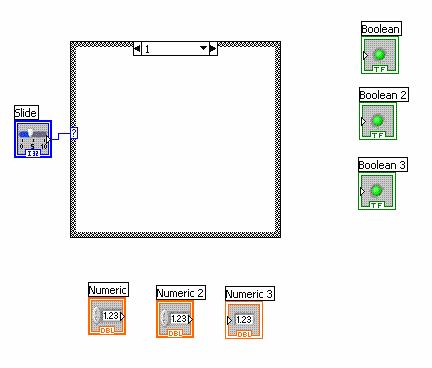 Figure 14: Back Panel Slide to Case Structure Connection
 - When the case
statement is created, it only has two cases. Since you have three operations
for the calculator, you need to make another case. To add the third case operation,
right-click anywhere on the case
structure and select Add Case After,
as shown in Figure 15.
 Figure 15: Adding Another Case
 - Now we'll add the mathematical operations that the calculator should perform for
each case. On the Functions Palette, click on the Arith/Compare
icon
 ' from the main Functions
Palette. This will bring up the Arith/Compare window shown in Figure 17.
' from the main Functions
Palette. This will bring up the Arith/Compare window shown in Figure 17.
 Figure 17: Arith/Compare Window
 - On the Arith/Compare window, click on the Numeric icon
 . This will bring up the Express Numeric window
shown in Figure 18.
. This will bring up the Express Numeric window
shown in Figure 18.
 Figure 18: Express Numeric Window
 - Click on the left arrow at the top of the case structure box. This should change the
caption for the case structure to 0. In the Express Numeric
Window, click on the Add icon
 , and click on a
location in the middle of the case structure box to place it.
, and click on a
location in the middle of the case structure box to place it.
- Click on the right arrow at the top of the case structure box. This should change the
caption for the case structure to 1. In the Express Numeric
Window, click on the Subtract icon
 , and click on
a location in the middle of the case structure to place it.
, and click on
a location in the middle of the case structure to place it.
- Finally, click on the right arrow at the top of the case structure box one more time,
changing the number in the caption to 2. In the Express Numeric
Window, click on the Multiply icon
 , and click on
a location in the middle of the case structure to place it. At this point, each case should
look like the ones shown in Figures 19a-c. You can check each case by clicking on the left and
right arrows to change the case number in the caption.
, and click on
a location in the middle of the case structure to place it. At this point, each case should
look like the ones shown in Figures 19a-c. You can check each case by clicking on the left and
right arrows to change the case number in the caption.
 Figure 19a: Case Structure: Addition Case
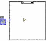 Figure 19b: Case Structure: Subtraction Case
 Figure 19c: Case Structure: Multiplication Case
- We now need to wire
the inputs of the calculator. First, set the case structure case to zero by
clicking on the left arrow until the caption reads 0. The triangle inside
should be addition, with a plus sign in the middle. Once again, click on the
"Connect Wire" icon on the Tools
Palette. Click on the leftmost Numeric icon, and click on the top left side of
the operation triangle to wire the first numeric input to the input of the
addition operation. Next, click on the second numeric icon, and on the left
bottom of the addition triangle, establishing the second input. Finally, click
on the right side of the triangle, and click on the third Numeric icon. This
will display the output of the addition calculation in the "Numeric 3" box on
the front panel. At this point you've completed having the calculator do
addition. Your back panel should look like Figure 20.
 Figure 20: Completed Back Panel for Addition
 - We now have to do the same thing for the other cases. Click on the right arrow next to the case structure caption. This will change the caption to 1, and the subtraction triangle will be in the middle of the case structure. As before, connect the first Numeric object to the top left of the triangle, the second Numeric to the bottom left of the triangle, and the right of the triangle to the Numeric 3 box at the bottom of the back panel. You can see the preceding step for details on how to do this if you need to. Finally, click the right arrow next to the case structure caption one more time. This will change the case number to 2, and the multiplication triangle will be in the middle of the case structure. Wire the Numeric objects to the triangle as you did for the other two case. At this point you have established the numeric inputs and outputs.
- We now to have to illuminate
the proper LED on the front panel corresponding to each operation. First, click
the left arrow to the left of the caption of the case structure until the
caption says "0, Default". First, we're going to repeat Steps 7 and 8 to bring
up the Express Numeric window: On the Functions Palette, click
on the Arith/Compare icon from the main Functions
Palette. On the Arith/Compare window, click on the Numeric icon .
This will bring up the Express Numeric window shown in
Figure 18. On the Express Numeric window, click the upward facing arrow. This
will bring up the Arithmetic and Comparison window shown in Figure 21.
Figure 21: Arithmetic and Comparison Window
- On the Arithmetic and Comparison window, click on the Boolean icon
 , which will bring up the Express Boolean
window shown in Figure 22.
, which will bring up the Express Boolean
window shown in Figure 22.
 Figure 22: Express Boolean Window
 - We are now going to
put three Boolean constants into the case structure. Since this is case 0,
which corresponds to add, we want to have the add indicator to be true, and the
other two to be false. We do this by clicking on the True Constant icon
 , and then clicking inside the case structure on the right
side to the left of the add indicator that's outside the case structure. We
then select the False Constant icon
, and then clicking inside the case structure on the right
side to the left of the add indicator that's outside the case structure. We
then select the False Constant icon  and place it inside the case structure on the right side next to the Subtract and Multiply indicators.
- We now need to wire
the constants to their respective indicators. Once again, click on the Connect
Wire icon on the
Tools Palette. Click on the right side of the top constant inside the case
structure and connect it to the top indicator by clicking on the indicator
next. Then do the same thing for the other two constants and their
corresponding indicators. We've now completed the Add operation. We still need
to do the other two operations.
- Click on the right arrow next to the case structure icon. The caption should
now show 1. We need to have the Subtract indicator illuminate for this
case. Once again, on the Functions
Palette, click on the Arith/Compare'
icon from the main Functions
Palette. On the Arith/Compare window, click on the Numeric icon .
This will bring up the Express Numeric window shown in
Figure 18. On the Express Numeric window, click the upward facing arrow. This
will bring up the Arithmetic and Comparison window shown in Figure 21. On the
Arithmetic and Comparison window, click on the Boolean icon
, which will bring up the Express Boolean window shown in
Figure 22.Click on the True Constant icon and click inside the right side of the case
structure to the left of the Subtract LED. Click on the False Constant icon and click inside the right side of the case
structure to the left of the Add LED, and again to the left of the Multiply
LED. Click on the Connect Wire icon on the Tools Palette.
Click on the right side of the top constant inside the case structure and
connect it to the top indicator by clicking on the indicator next. Then do the
same thing for the other two constants and their corresponding indicators.
We've now completed the Subtract operation.
- We're now ready to finish the calculator. Click on the right arrow next to the case structure
icon. The caption should now show 2. We need to have the Multiplication
indicator illuminate for this case. Once again, on the Functions Palette, click
on the Arith/Compare icon . On the Arith/Compare window,
click on the Numeric icon . This will bring up the Express Numeric window shown in
Figure 18. On the Express Numeric window, click the upward facing arrow. This
will bring up the Arithmetic and Comparison window shown in Figure 21. On the
Arithmetic
and Comparison window, click on the Boolean icon which will bring up the Express Boolean window shown in
Figure 22. Click on the True Constant icon and click inside the right side of the case structure
to the left of the Multiplication LED. Click on the False Constant icon and click inside the right side of the case
structure to the left of the Add LED, and again to the left of the Subtraction
LED. Click on the Connect Wire icon on the
Tools Palette. Click on the right side of the top constant inside the case
structure and connect it to the top indicator by clicking on the indicator
next. Then do the same thing for the other two constants and their
corresponding indicators. We've now completed the Multiply operation.
- Before moving on, make sure that the boxes on the edges of the case
structure are filled in. If they are not, that box has to be wired in
all cases defined by the user. Your back panel should look like Figure 23.
 Figure 23: Completed Calculator Back Panel
- Drag all the Boolean nodes to the right edge of the window and all numeric controls and
indicator to the bottom of the window. Place the slide node on the left edge of the window.
This will leave a large area in the middle that you will fill in at the next few
steps. Your back panel should now look like Figure 11.
- At least one case statement to control the arithmetic operations. This case statement
will be the heart of the calculator. Here's how you do it:
- After you have created your VI, it must be tested:
- Enter different input numbers through the control icon on the front panel.
- Make sure the output is correct.
- Make sure the correct LED lights up for the operation.
- Have your TA test your VI.
 Figure 24: Completed and Working VI
 - Once testing is completed:
- Print the VI you have created.
- Have your TA sign it.


Design 2: Heating and Cooling System
Build a VI that simulates a heating and cooling system. Your system must be controlled either manually or automatically. Design your VI so that:
- The air conditioner is turned on when the temperature is above 80°F.
- The heater is turned on when the temperature is less than 60°F.
- The heater and the air conditioner are turned off when the temperature is between 60°F and 80°F.
- The front panel must contain:
- Three LEDs: one to represent the AC, one to represent the heater, and one to show that the system is being operated manually.
- Three switches: one to control the AC, one to control the heater, and one to control manual or automatic operation.
- A thermometer to set the temperature of the system. By default, the thermometer is an indicator; right-click on it and select Change to control. The thermometer should be set to 70°F.
- The back panel must contain:
- A Boolean case statement to control the manual and automatic operation of the AC and the heater.
- After you have created your VI, it must be tested:
- Using the slide bar on the thermometer, change the system temperature. Make sure the AC and heat come on as directed.
- Test the program's manual operation by turning the manual switch on and then turning the AC and heat switches on. Each of the LEDs should light up when its corresponding switch is in the On position.
- Have your TA test your VI.
- Once testing is completed:
- Print the VI you have created.
- Have your TA sign it.
- Save your VI. You'll be using it again in Lab 6.
Design 3: Lighting System
Build a VI that simulates a lighting system in a house with 4 rooms. Your design must include 4 lights (LEDs) and at least 5 switches – one switch per light and one "master" switch which will turn all of the lights off simultaneously (think of this as a circuit breaker). Your program should also interact with real LEDs attached to a DAC board.
- The front panel of your program should include 5 switches and 4 virtual LEDs.
- While there are several ways to implement the back panel, one suggestion is to use a separate Boolean case structure for each switch. This will also make it easier to interact with the LEDs attached to the DAC board.
- In order to control the LEDs attached to the DAC board, a DAQmx Assist node is required on the back panel. The LEDs will be connected to pins 52, 17, 49, and 47 (and pin 35 for ground).
- DAQmx Assistant is found in the Functions Palette, under Measurement I/O -> NI-DAQmx. (see Figures 25a-d)
 Figure 25a: Functions Palette. Click on the pull down arrow at the bottom of the Functions Palette to see all the categories available.
 Figure 25b: Full Functions Palette with the Measurement I/O category pointed out
 Figure 25c: Measurement I/O category with DAQmx pointed out
 Figure 25d: DAQmx palette with DAQ Assist circled
 - Once you have placed these on the back panel, the DAQ Assistant dialog box will open. Follow Figures 26a-e to set up the DAQmx Task.
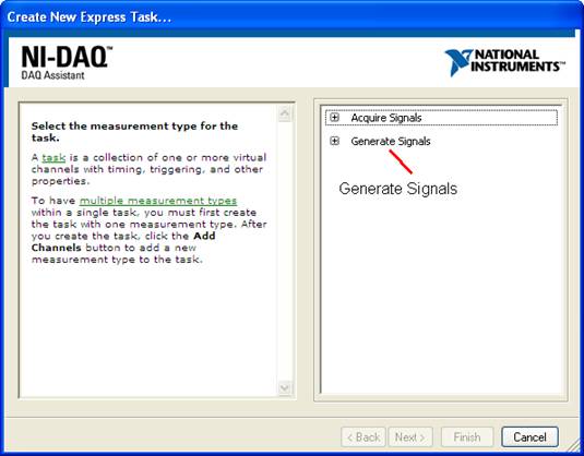 Figure 26a: Select Generate Signals
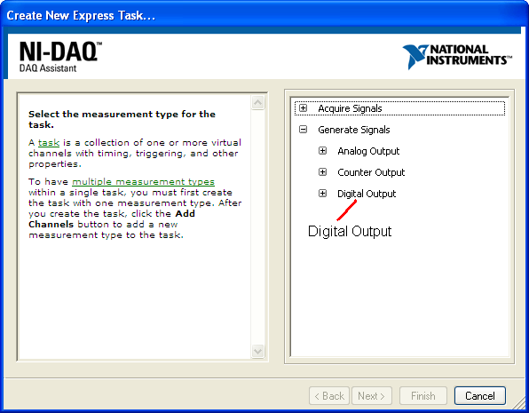 Figure 26b: Select Digital Output
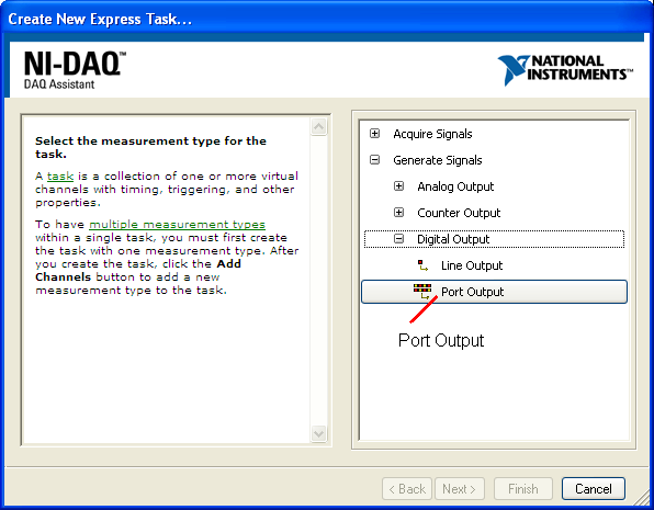 Figure 26c: Select Port Output
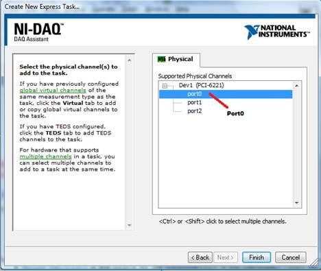 Figure 26d: Select port0
 Figure 26e: Click OK
 - The DAQ Assistant, depending on how it's set up, is used for reading or writing information from or to the DAC board. In our case, we only see the one terminal labeled data.
 Figure 27: DAQ Assistant
- data (integer array): This determines which pins on the DAC board will be activated (in other words, which LEDs will light up).
- Each pin is represented by a number that is a power of 2 (see Pattern Table). For example, sending a value of 1 will light up the LED connected to pin 52.
- To light up more than one pin at a time, add the values of each pin together and use the sum. For example, sending a value of 3 to the Pattern will result in the LEDs connected to pins 52 and 17 to light up.
- data (integer array): This determines which pins on the DAC board will be activated (in other words, which LEDs will light up).
- If you used separate Boolean case structures for each switch, then setting up the pattern for DAQ Assistant can be achieved as follows:
- In each Boolean case, if the switch is off, place a numeric constant of 0.
- If the switch is on, then include a numeric constant of the appropriate value (see Pattern Table). For example, the switch corresponding to pin 52 should have a numeric constant of 1.
- Once every Boolean case structure has a numeric constant in it, they must all be added together. This can easily be achieved using the Compound Arithmetic operator.
Don't forget to wire both the numeric constant in the True case and the numeric constant in the False case.
- The output from the Compound Arithmetic operator should be wired to a Build Array icon. Depending on your background, you may or may not understand what an array is, but that is not important. Conceptually, think of a line of people waiting to get in to a movie theater. In our case, the movie theater is the data terminal on the DAQ Assistant icon and the line is the array. This movie theater doesn't care if there is one person in line or if there are a million people on line: it just wants a line. In our case there will only be one person on line or rather only one element in the array: the result of the Compound Arithmetic operator. Build Array can be found in the Functions Palette, under Proramming -> Array. (see Figures 28a-c)
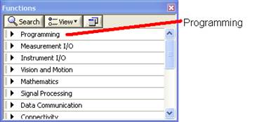 Figure 28a: Full Functions Palette with the Programming category pointed out
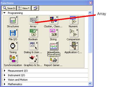 Figure 28b: Programming category with Array pointed out
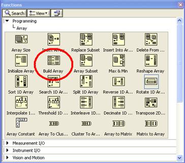 Figure 28c: Array palette with Build Array circled
 - Also keep in mind that if the master switch is off, then all of the LEDs connected to the DAC board should shut off as well.
- DAQmx Assistant is found in the Functions Palette, under Measurement I/O -> NI-DAQmx. (see Figures 25a-d)


| Pattern | ||||||||
|---|---|---|---|---|---|---|---|---|
| 128 | 64 | 32 | 16 | 8 | 4 | 2 | 1 | |
| Port | Corresponding Pin Number | |||||||
| 1 | 48 | 16 | 51 | 19 | 47 | 49 | 17 | 52 |
Your lab work is now complete. Please clean up your workstation. Return all unused materials to your TA. Refer to section #3 Your Assignment for the instructions you need to prepare your lab report.
LabVIEW Digest of Common Tasks
Front Panel Controls and Indicators
How to get a slide control:
- On the Controls palette, select the Num Ctrls icon
- Select Horizontal Pointer Slide
- Click on the front panel to place the slide on the front panel at the location you select
How to get a LED indicator:
- On the Controls palette, select the LEDs icon .
- Select the Round LED icon from the icons shown.
- Click on the left window to place the LED on the front panel at the location you select.
- Rename the LED with a label that indicates what the LED stands for. To rename the LED,
click on the Edit Text icon on the Tools
palette. Then click on the 'Boolean' label on each LED and replace it with
the proper text.
How to get a Numeric Input Control
- On the Controls palette, click on the Num Ctrls icon. This will bring up the window shown in Figure 5.
- Click on the Num Ctrl icon and click on the location where you want to place the control.
How to get a Numeric Indicator Output
- On the Controls palette, click on the Num Inds icon .
This will bring up the window shown in Figure 9.
- Click on the Num Ind icon and click on the front panel location where you want the indicator.
Back Panel Objects
How to define a case structure
- In the block diagram (back panel) of LabVIEW, go to the menu bar, select window,
and choose "Show Functions Palette", just as shown on Figure 29a. This will bring up
the Functions Palette, shown in Figure 29b.
Figure 29a: How to bring up the Functions Palette Figure 29b: Functions Palette
- Clink on the Exec Ctrl icon. This will bring up the Exec Ctrl window, shown in Figure 13.
- Click on the Case Structure icon. Click on the right window to locate it on the back panel.
- The default is two cases: 0 and 1. To add more cases, right-click anywhere on the case structure and select Add Case After, as shown in Figure 15.
- Define what happens for each case. On each side of the caption are arrows that will count the case number up and down. Choose the case number you want to define and then fill in the case structure with whatever needs to be done for this case. Make sure every case is fully defined. It is very easy to forget things.
How to define an arithmetic operation
- On the Functions Palette, click on the Arith/Compare
icon . will bring up the Arith/Compare window shown
in Figure 17.
- On the Arith/Compare window, click on the Numeric icon .
This will bring up the Express Numeric window shown in Figure 18.
- In the Express Numeric Window, click on the icon for the arithmetic operation you want. Click on the front panel location where the icon goes.
How to define Boolean constants (usually used to illuminate LEDs)
- On the Functions Palette, click on the Arith/Compare
icon . This will bring up the
Arith/Compare window.
- On the Arith/Compare window, click on the Numeric icon
. This will bring up the Express Numeric window
shown in Figure 18. On the Express Numeric window, click the
upward facing arrow. This will bring up the Arithmetic and Comparison
window shown in Figure 21.
- On the Arithmetic and Comparison window, click on the Boolean icon
, which will bring up the Express Boolean
window shown in Figure 22.
- Click on the True Constant icon or False Constant
icon , and then clicking the location of the constant
on the back panel.
How to wire things
- Objects have inputs on their left side and outputs on their right side. You always wire the output (right side) of one object to the input (left side) of another object.
- On the Tools Palette, chose the "Connect Wire" icon .
- Click the object output that you want to wire from. Click the object input you want to wire to. The first object's output is now connected to the second object's input.
Footnotes
1 Introduction to LabVIEW, Six-Hour Course [Courseware]. (June 2003) Austin, TX: Worldwide Technical Support and Product Information, National Instruments Corporation