Introduction to 3D Printing AutoCAD
Objective
In this exercise, drafting software used by technical professionals will be introduced. Basic technical design methods will be shown using Computer-Aided Design (CAD) software, specifically AutoCAD. Later on, this knowledge can be incorporated in the semester-long design project by constructing physical prototypes with 3D printing.
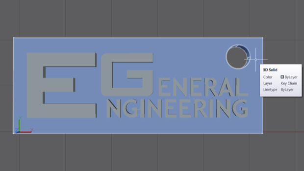
To practice this prototyping procedure, a EG Logo keychain will be created in AutoCAD to export for a 3D print. The members of the winning team of Lab 1C: Mousetrap Vehicle Competition will each receive a 3D-printed keychain.
Overview
Computer-Aided Design
CAD programs (AutoCAD, Inventor, Revit, SolidWorks, SketchUp) allow engineers to make precisely scaled drawings. These drawings can be used to manufacture equipment and construct infrastructure. CAD drawing allows designers to display designs with complete specifications and detail. Orthographic views (top, bottom, side, front, back, etc.) can be used to document every aspect of the technical drawing needed for production. Isometric views can be used to interpret the final 3D representation of the product.
This exercise will teach the components of CAD software, file formats, and the basics of 3D drafting. It will provide enough information to learn how to create drawings, as well as explore the other tools and functions.
Additional AutoCAD instruction can be found in the AutoCAD Skill Builder
3D Printing
3D printing allows for rapid prototyping and onsite manufacturing of products. Plastic 3D printing has led the way for new techniques using metals and biomaterials. As materials science engineering develops, more materials will be incorporated into 3D printing techniques.
In this class, 3D printing can be used to produce a team logo for the semester-long design project.
Procedure
Setting up the file
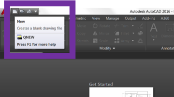
- Start AutoCAD and open a new file.
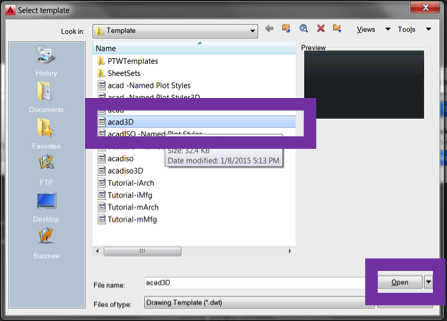
- Select the AutoCAD 3D template.
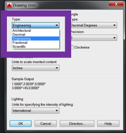
- Modify the units for the drawing.
- Change the length unit type to Engineering.
File formats and viewing mode
- AutoCAD drawing files formats:
- DWG – the primary drawing file for the 3D model view
- STL – the file exported from AutoCAD for input into 3D printing software
- DWT – the file of the sheet set seen in the layout view
- DXF – a drawing format for compatibility with other software
- PLT – the file sent to the printer of the layout view
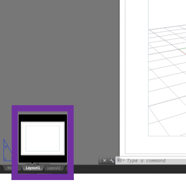
- Click on the layout view as the default AutoCAD view is model view.
- Change to model space in the layout view to change the viewport.
Designing the EG Keychain
- Download and open the EG Logo Template.
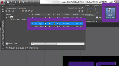
- Open the layer properties and click the lightbulb next to the EG Logo layer.
- Layers are a useful way to separate different components of a drawing file.
- In this DWG, the EG Logo layer is the image file used to create the text outline.
- Separating model features (e.g. plumbing and electrical) allows separate viewing.
- Turn the EG Logo layer back off by clicking the lightbulb.
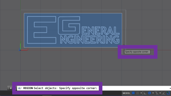
- Fill the EG Logo text outline by typing the command REGION. Use Figure 8 to help determine the selection area.
- In general AutoCAD commands operate with the same basic steps.
- Type the command.
- Choose command parameters and objects.
- Select object (hit enter after).
- Enter quantity (type and hit enter).
- Specify position (click on screen).
- Hit the enter key to execute command.
- Remove the inner holes (the counter-space) of the letters A and R in the EG logo.
- Move the letters to the back by using DRAWORDER, select the Rs and As, hit enter, and select back in the command line. This will move the outlines of the letters back and allows you to select the inner parts of each letter.
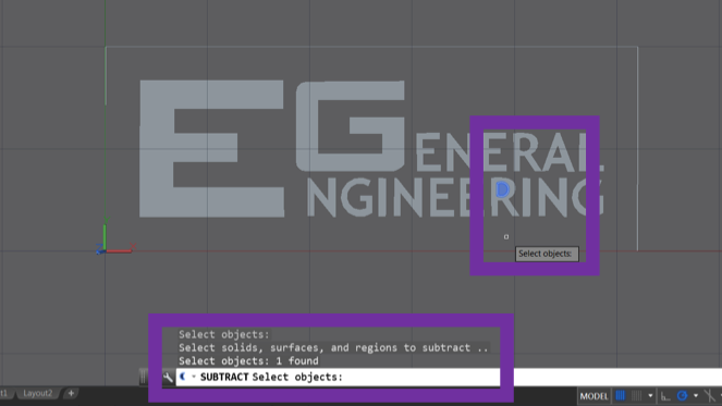
- Input SUBTRACT into the command line and hit enter. SUBTRACT is composed of two parts. Selecting the region to remove from and what needs to be removed.
- Select all of the As and Rs and hit enter. (Note: these will still have the insides filled)
- Select the inside regions you want removed and hit enter.
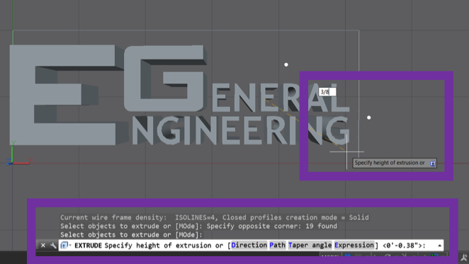
- Use the EXTRUDE command to add 3/8” height to the text.
- Use the REGION command on the box outline and EXTRUDE to 1/4”.
- Create a keychain hole.
- Draw a CIRCLE with radius 1/8”.
- Change the DRAWORDER of the box to the back.
- EXTRUDE the circle -1/4”.
- Change the DRAWORDER of the box to the back.
- SUBTRACT the cylinder from the box.
- Select all features and publish or export as an STL file.
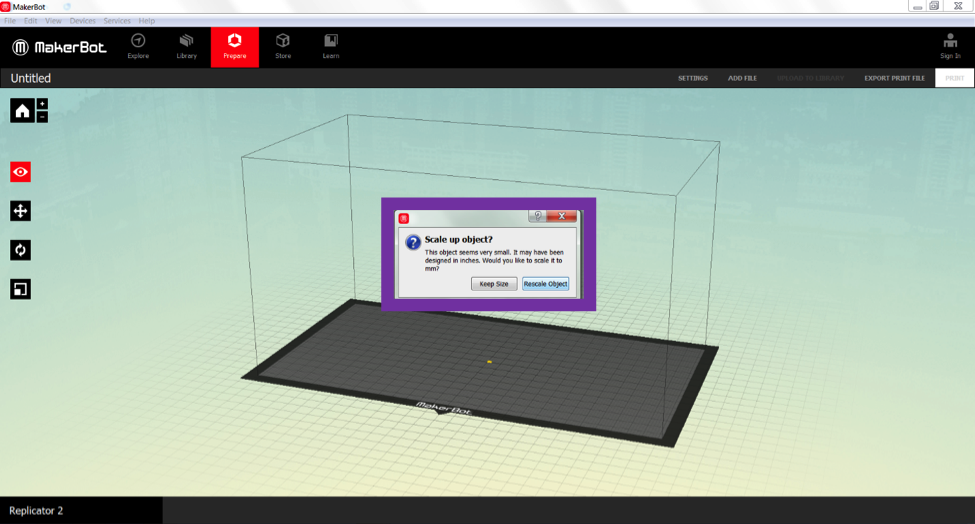
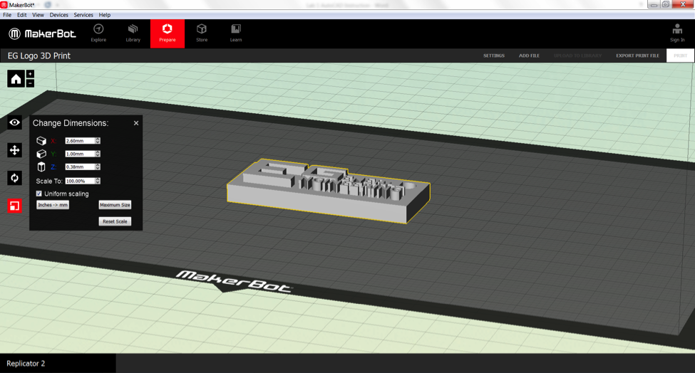
- Open the STL file in MakerBot Desktop, click rescale object to convert from inches to millimeters.
- Explore the features of 3D printing software (scaling, position, rotation).
| ||||||||
