Makerbot Guide
Makerbot Guide
Makerbot Desktop Software is a critical piece of software for our 3D Printers. STL files do not contain the instructions that the printer needs to position the extruder; to do this Makerbot Desktop “Slices” the model. This process analyses the 3D models that have been imported and slices them into individual layers that the printer can lay down. The software also determines which extruder to use (which decides which color of filament is used).
Toolbar
The toolbar on the left side of Makerbot Desktop allows some final adjustments to the object before slicing. There are 5 main model tools:
- View – Rotates the view of the camera to specific views such as top, side and front as well as Isometric (Reset view)
- Position – Translate the model in the X, Y and Z dimensions (in millimeters). Can also center the object on the platform and move objects down onto the platform (On platform)
- Rotation – Rotate the model in the X, Y and Z dimensions (in degrees). Can also automatically adjust to place the nearest flat edge on the platform (Lay Flat)
- Dimensions – Scale the model in the X, Y and Z dimensions (in millimeters). Can also scale by a percentage (Scale To), autoscale from inches to mm (Inches -> mm), autoscale to the largest pritable size (maximum size), or reset the part to its original size (reset scale)
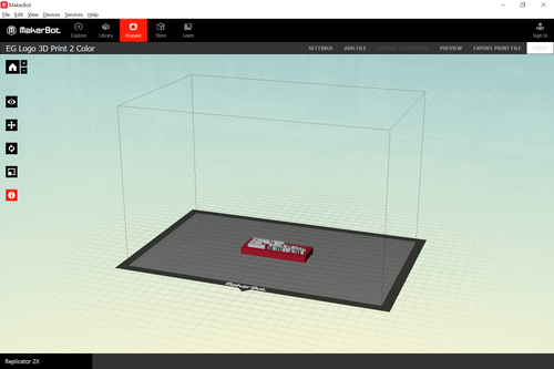
- Information – Select which extruder is used for the model this determines what color the model will be.
Importing Files
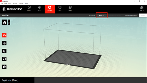
To create a multicolor print at least two STL files must be imported, each file will use one extruder. To import the first file click the “Add File” button.
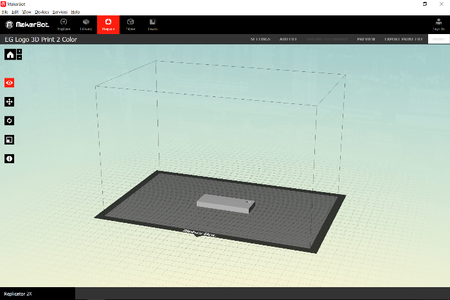
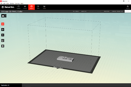
Select one of the two files that is used in the design, it should load into the model viewer. Next add the second file using the same method.
The two files sometimes load inside one another and will have to be moved. Make sure when moving the parts that the two pieces are flush with one another for printing, this insures that the print will remain solid after switching extruders.
Selecting Colors
To change the color that the parts will print the only necessary step is to change the extruder that is set for one of the parts. By default parts printed by the right extruder will appear white while parts printed by the left extruder will appear red (this can be changed under Edit >> App Settings>> Display Settings). Change all of the parts that should be one color to be the same extruder and make note of what color each extruder should be because this will be necessary when submitting the design (In this case left would be purple and right would be white). If you do not see the information option change the setting under Devices >> Select Type of Device to Repliciator(Dual).
Checking Material Use
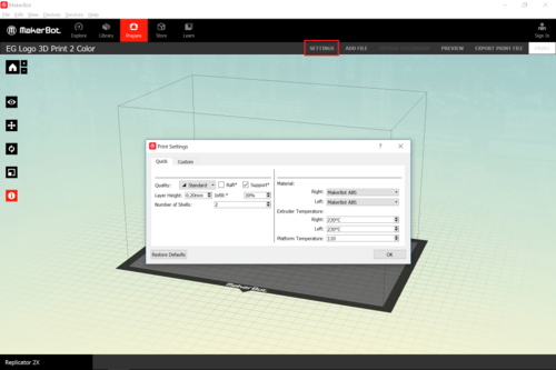
Once everything is placed correctly and the extruders have been selected it is necessary to check that the print is within the maximum material use. To get an accurate usage reading the print settings need to be set correctly. Click settings and set the settings to the following:
- Quality: Standard
- Raft: Unchecked
- Support: Checked
- Layer Height: 0.2mm
- Infill: 30%
- Number of Shells: 2
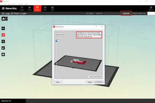
Next close out of the settings window and click on preview. The software will now process and slice the model and show a layer-by-layer preview of the print. In the top right corner of the preview the software shows left and right material use. Make sure the sum of these numbers is less than the maximum material use. If the material use is too high the model can either be rescaled or redesigned until it meets the requirements.
Once the material usage has been verified and coloring has been selected save the file as a .thing under file >> save (or by pressing Ctrl + S).
