AutoCAD Skill Builder
| This page is currently being edited and reorganized to improve clarity. No content is being added or removed, and the edits will not affect the procedure performed during the lab. While the page is being reorganized, figure numbers may not match up correctly and may repeat as well. If this happens, and you become confused as to which figures are being referred to, please ask your TA for assistance and/or clarification. |
Objective
In this exercise, you will be introduced to additional software used by technical professionals. You will learn basic technical design methods using Computer-Aided Design (CAD) software, specifically AutoCAD. Later on in the course, you will use this knowledge to create designs, particularly in your semester-long design project.
Overview
In any design process, engineers must put their ideas on paper, usually in the form of a sketch. This initial drawing is done in pencil without rulers or straight edges. It shows some detail, for example, blocks represent objects and double parallel lines represent walls. The type of line used to draw an object is important because it indicates what is to be built. Here is a list of some types of lines and their uses:
The construction line is the one used most frequently in technical drawings. It indicates solid objects like walls.
The hidden line is used to show hidden objects like wiring in walls.
This line is used to indicate dimensions.
This line is used to show the center of circles and curves on a drawing. Contractors are able to locate the center of the circle when this type of line is used.
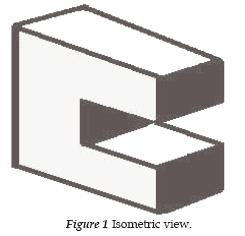
These line types are used together to create a picture of the design. This picture can be isometric or orthographic. An isometric drawing is a three dimensional view. See Figure 1.
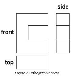
An orthographic drawing is a two dimensional view from different perspectives. There are usually three views - top, front and side. See Figure 2.
Computer-Aided Design
Computer-Aided Design (CAD) programs allow engineers to make precise scaled drawings in less time than more traditional methods. CAD drawing allows designers to make changes easily and efficiently making them more productive. You will need to understand the fundamentals of Computer-Aided Design to progress in your career.
This exercise has been designed to introduce the basics of CAD drawing.
Starting and Setting Up AutoCAD
Start AutoCAD 2010. (Note: It is best to have a 3 button mouse.)
Note: Beginning with AutoCAD 2010, Autodesk has changed the toolbar interface to more closely resemble that of Microsoft Office's ribbon interface.
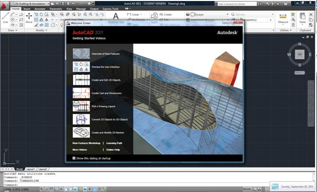
Once the program has loaded, you can close the Welcome Screen. Note that the tutorials on the left hand side are very useful and should be reviewed later on.
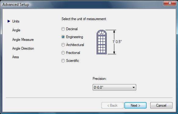
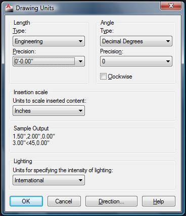
In the command box (bottom of the screen) type units and the Drawing Units dialog box will appear (see Figure 4).
For the length unit, select the type to be Engineering and choose the precision to be two decimal places. Then click next (See Figure 5).
Setting Up the Dimensions and the Text Style
Later on, we will be inputting text and dimensions into our drawing. However, it is best to set up a general style for the drawing due to the fact that the default settings are not sufficient for our needs.
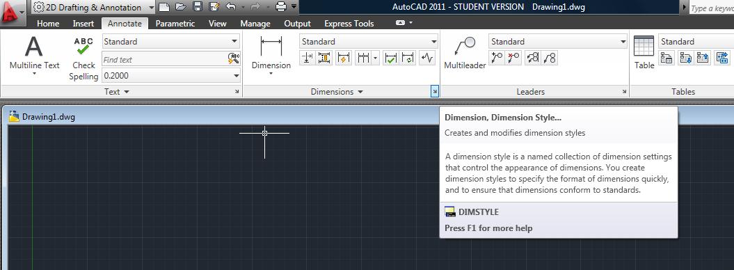
First, select the Annotate tab on the ribbon. Click the arrow at the lower right-hand corner of the Dimensions group to access the Dimension Style Manager dialog window. (See Figure 11)
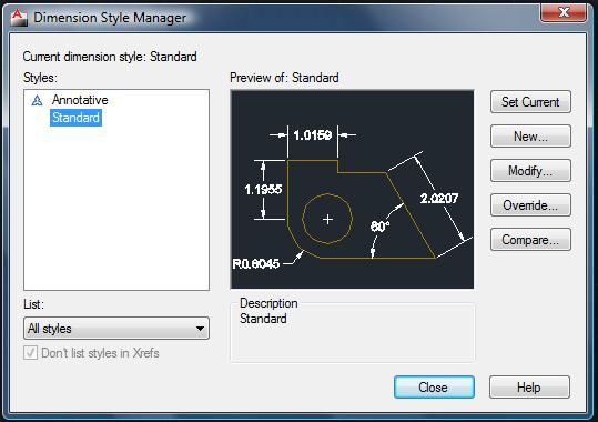
In the Dimension Style Manager window, select Modify.... (See Figure 12)
Under the Lines tab, change the following:
- Offset from origin: 1'
Under the Symbols and Arrow tab, change the following:
- Arrow Size: 1'
Under the Text tab, change the following:
- Text Height: 1'
Under the Primary Units tab, change the following:
- Unit Format: Engineering
- Precision: 0'-0.00"
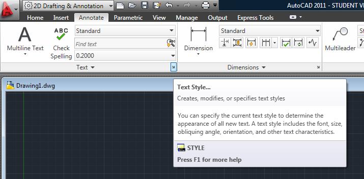
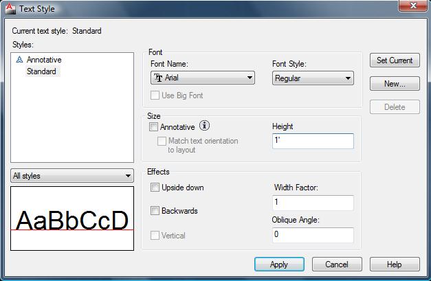
To change the text style, click the arrow at the lower right-hand corner of the Text group of the Annotate tab on the ribbon. (See Figure 13)
You may choose the type of font and change the height to 1' as shown below in Figure 14.
Command Window
At the bottom of the screen, you see a separate window showing a few lines of text. (You can change it to show as many lines as you like by dragging the top edge of the window up or down.) Notice the word Command. This is the command line. All commands can be executed by typing them on the command line. Even if you use a menu item or toolbar button to execute a command, you may need to look at the command line to see how AutoCAD responds. Often, AutoCAD provides options that must be typed in from the keyboard. Also, text that you type appears on the command line. For example, when you type in coordinates specifying a point, they appear on the command line. To see more of the command line, press F2 to open the AutoCAD Text window. You can scroll back through previous commands. Press F2 again to close the window. (See Figure 15)
To Draw a Line
- Type line or l in the command window, then Enter, or click the Line icon [
 ] in the Draw group under the Home tab.
 - Click the point where you want the line to begin. Drag the line in the direction you want it to go, and specify its length when prompted. Hit Enter.
- Press Escape to exit the line command.
Note: Most of the commands can be done by clicking an icon or typing into the command window.
Drawing Lines with Specific Angles and Lengths
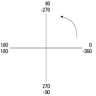
Relative polar coordinates take the form distance<angle.
By default, angles are measured according to Figure 16.
In order to draw a line that is 10' at a 30º angle:
- Click on the Line icon [
 ].
]. - Click the point where you want the line to begin.
- Press Escape to exit the Line command.
Then type in the Command Window: distance<angle. Hit Enter.
EX: 10'<30, then hit Enter
Below the Command Window
From left to right: Infer Constraints, Snap Mode, Grid, Ortho Mode, Polar Tracking, Object Snap, 3D Object Snap, Object Snap Tracking UCS, Allow/Disallow Dynamic, Dynamic Input, Show/Hide Lineweight, Show/Hide Transparency, Quick Properties, Select Cycling.
- When in orthogonal mode—ortho mode as it's called for short—you can only draw orthogonal (right angles) lines with the mouse. Ortho mode also affects editing. For example, with ortho mode on, you can only move objects vertically or horizontally. Combined with snap and grid, ortho mode makes drawing easier and more efficient. Ortho mode is also great for direct distance entry. Click ORTHO on the status bar to toggle ortho mode on and off. You cannot have polar tracking on at the same time that ortho mode is on.
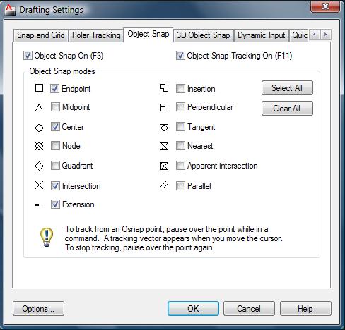
- Object snap (osnap) allows a user to precisely acquire certain points on a line or object to be able to manipulate the drawing, such as aligning or attaching those points that are selected to other points.
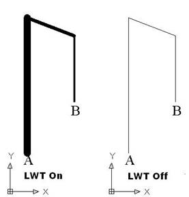
- LWT is the Lineweight function, and it controls the width of the line. A lineweight can help to distinguish various elements of your drawing, both on-screen and on paper. For example, you could use a thicker lineweight to indicate planned construction changes, for dimension lines, or even to represent the true width of an object. The LWT button on the status bar turns on and off the display of lineweights. By default, LWT is off. (See Figure 21)
Example:
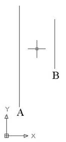
In order to draw a line from endpoint A to endpoint B in Figure 17 accurately and ensure that we are actually attaching the ends of the lines and not the space before, near, or around it, we utilize a command called "osnap".
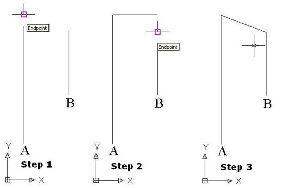
To toggle osnap on and off, click the "OSNAP" button. Figure 18 shows the use of osnap.
Step 1: Click on the line icon [ ![]() ] and
when you situate the crosshair at the endpoint of line A and you will notice a pink
or green box appear. This means that the endpoint has acquired by AutoCAD.
] and
when you situate the crosshair at the endpoint of line A and you will notice a pink
or green box appear. This means that the endpoint has acquired by AutoCAD.
Step 2: Once the endpoint of line A has been acquired, click and move the crosshair to the end of line B. You will notice that the endpoint of line B has been found by AutoCAD.
Step 3: Click and press enter to complete the line command function.
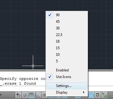
Note: To click on different points of a line, you will need to change the osnap settings. In order to go to the settings of osnap, you will have to right click on any part below the command window and a context menu will appear. See Figure 17.
Select settings and then you can choose the settings for which option you would like to change. (See Figure 20)
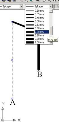
In order to select the line width of a line, first select the line(s) and then click on the Line Weight Control and select the desired thickness as show in Figure 22.
Offsetting Objects
The Offset command creates lines or curves parallel to one
existing object. The beauty of this command is apparent when you start to
create complex objects, such as polylines. Polygons
and rectangles are polylines, meaning that they are
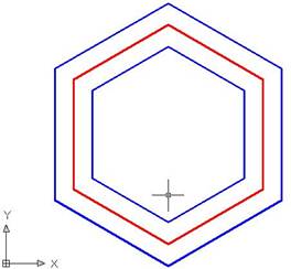
treated as one object. Using OFFSET, you can create concentric polygons, for
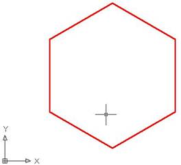
example the figure below shows three concentric polygons. The red polygon was
created with the POLYGON [ ![]() ] command, which is found under the Home tab by clicking the arrow at the bottom right corner of the Draw group and selecting the polygon button shown above. The blue polygon was subsequently created by using OFFSET as
shown in Figure 23.
] command, which is found under the Home tab by clicking the arrow at the bottom right corner of the Draw group and selecting the polygon button shown above. The blue polygon was subsequently created by using OFFSET as
shown in Figure 23.
Example:
To offset a line or an object:
- Click
 , found under the Home tab in the Modify group, and then on the command window specify
offset distance and then press Enter.
 - Select the object and click in the direction you would like the object to be offset.
Drawing Arcs
To draw an arc, choose Arc [ ![]() ] from the
Draw toolbar and follow the prompts. As with circles, object snaps are often
helpful when drawing arcs.
] from the
Draw toolbar and follow the prompts. As with circles, object snaps are often
helpful when drawing arcs.
When drawing an arc by using the Start, End, and Radius options, the three specifications actually define two possible arcs, one minor and one major. AutoCAD draws the minor arc by default, in the counterclockwise direction. (A minor arc is less than half a circle.) If you enter a negative number for the radius, AutoCAD draws the major arc (which is more than half a circle). The options requiring an angle also define two possible arcs, one drawn counterclockwise and one drawn clockwise.
AutoCAD draws the counterclockwise arc by default. If you type a negative number for the angle, AutoCAD draws the arc clockwise.
Rotating an Object
To rotate an object, choose Rotate [ ![]() ] from the
Modify toolbar and select an object. Alternatively, select an object and then
choose Rotate from the Modify toolbar. At the Specify base point: prompt from
the command window, indicate the point around which you want to rotate. At the
Specify rotation angle or [Reference]: prompt, type an angle at the command
line.
] from the
Modify toolbar and select an object. Alternatively, select an object and then
choose Rotate from the Modify toolbar. At the Specify base point: prompt from
the command window, indicate the point around which you want to rotate. At the
Specify rotation angle or [Reference]: prompt, type an angle at the command
line.
The Reference option lets you specify an absolute existing rotation angle and the desired angle. At the Specify the reference angle <0>: prompt, you type in an angle or specify an angle by picking two points. These can be object snap points on the object that specify the object's current angle. At the Specify the new angle: prompt, type or pick a new angle. You can also pick an object snap on another object in the drawing to indicate this new angle. You can use the Reference option to align the object with the X or Y axis or with another object in your drawing.
Mirroring Objects
Many drawings have symmetrical elements. Often, especially in mechanical drawing, you can create one-half or one-quarter of a model and complete it simply by mirroring what you have drawn.
To mirror, select an object or objects and
then choose Mirror [ ![]() ] from the
Modify toolbar. Alternatively, choose Mirror from the Modify toolbar and
then select an object or objects.
] from the
Modify toolbar. Alternatively, choose Mirror from the Modify toolbar and
then select an object or objects.
AutoCAD prompts for the first and second points of the mirror line. This is an imaginary line across which AutoCAD creates the mirrored object. The length of the line is irrelevant — only its start point and direction are important.
Note: Most mirror lines are orthogonal. Therefore, after you specify the first mirror point, turn on ORTHO and move the mouse in the direction of the second point. You can then quickly pick the second point. Polar tracking can also easily guide you to specify an orthogonal mirror line.
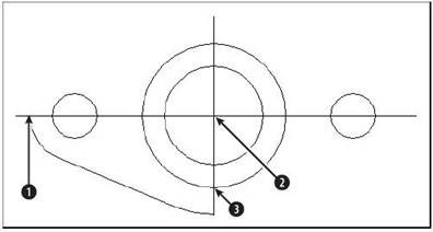
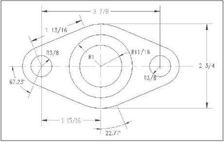
Example based on a mounting plate shown in Figure 24
- Choose Mirror from the Modify toolbar. Select objects: prompt appears at the command window. Pick the exterior line and two arcs and press Enter.
- At the Specify first point of mirror line: prompt, pick the intersection
 in Figure 24. At the Specify second point of
mirror line: prompt, pick the intersection
 .
. - AutoCAD prompts: Delete source objects? [Yes/No] <N>: Press Enter to accept the default, No.
- Again choose Mirror from the Modify toolbar. At the Select objects: prompt, type P and then press Enter to pick the original lines. Then pick the new exterior line and two arcs and then press Enter.
- At the Specify first point of mirror line: prompt, pick the intersection
 . At the Specify second point of mirror line:
prompt, pick the intersection
 . Press
Enter again at the Delete source objects? [Yes/No] <N>: prompt.
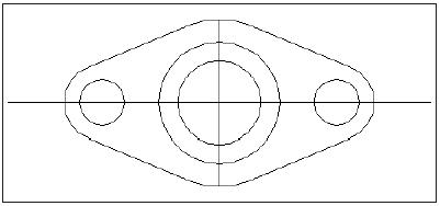
 - AutoCAD completes the mounting plate seen in Figure 25.
Trimming objects
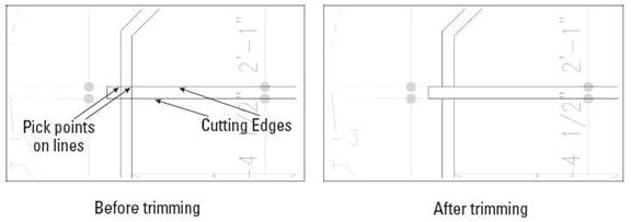
As you edit a drawing, you may find that lines or arcs that once perfectly met other objects now hang over. To trim an object, you must first specify the cutting edge, which defines the point at which AutoCAD cuts the object you want to trim. You define the cutting edge by selecting an object. You can select several cutting edges and several objects to trim at one time, as shown in Figure 26. When you select an object to trim, you must pick the object on the side that you want trimmed (not on the side that you want to remain). A common use for the TRIM command is to create intersections of walls in architectural floor plans.
While using the TRIM command, you can switch to extending objects by pressing the Shift key as you select objects to trim.
To trim an object, choose Trim [ ![]() ] from the
Modify toolbar. You cannot select objects before starting the TRIM command.
AutoCAD displays the Current settings:
Projection=UCS, Edge=None,
Select cutting edges ... Select objects: prompt. AutoCAD lets you know the
values of the two system variables that affect trimming. The Projection setting
is used only for 3D models. The Edge setting is used for implied intersections.
When Edge is set to Extend, AutoCAD trims to the implied intersection of the
cutting edge and the object to be trimmed. At this prompt, pick the object(s)
that you want to use as a cutting edge. Press Enter to end object selection. (See
Figure 26)
] from the
Modify toolbar. You cannot select objects before starting the TRIM command.
AutoCAD displays the Current settings:
Projection=UCS, Edge=None,
Select cutting edges ... Select objects: prompt. AutoCAD lets you know the
values of the two system variables that affect trimming. The Projection setting
is used only for 3D models. The Edge setting is used for implied intersections.
When Edge is set to Extend, AutoCAD trims to the implied intersection of the
cutting edge and the object to be trimmed. At this prompt, pick the object(s)
that you want to use as a cutting edge. Press Enter to end object selection. (See
Figure 26)
Now you may be able to cut the lines within the cutting edges. Use the Undo (CTRL+Z) option, or type u then press Enter, if the results of the trim are not what you want. You can then continue to select objects to trim.
Layers
The best way to organize your drawing into colors, linetypes, and lineweights is to use layers. Layers offer powerful features that enable you to distinguish all the various elements of your drawing. In an architectural drawing, for example, common layers are walls, doors, windows, plumbing, electrical, fixtures, structural elements, notes (text), dimensions, ceiling, insulation, posts, title block, and so on. Mechanical drawings might use center, hidden, hatch, object, and title block layers. Each discipline has its own conventions, and you might have specific conventions where you work.
Besides having a color, linetype, and lineweight, every layer must have a name. All drawings come with a default layer, called layer 0 (zero). Its color is Black/white, its linetype is Continuous, and its lineweight is Default. (The lineweight for Default is 0.010 inch or 0.25 mm.) All the exercises in this book up to this point have used layer 0. To create a new layer, you must give it a name, a color, a linetype, and a lineweight. You can then start drawing on that layer.
Layers also have four states. These states control visibility, regeneration, editability, and plottability of layers:
- On/Off: On layers (the default) are visible. Off layers are invisible and are regenerated with the drawing.
- Thawed/Frozen: Thawed layers (the default) are visible. Frozen layers are invisible and are not regenerated with the drawing. However, when you thaw a frozen layer, it requires regeneration. If you have floating viewports, you can also freeze a layer just in the current viewport, or only for new viewports that you create.
- Unlocked/Locked: Unlocked layers (the default) are visible and editable. Locked layers are visible but cannot be edited.
- Plottable/Not Plottable: Plottable layers are plotted. Not plottable layers are not plotted. This setting affects only layers that are on or thawed because off and frozen layers are not plotted anyway.
Creating a new layer:
To create a new layer, select the Layer Properties Manager [ ![]() ] from the
Layers group under the Home tab.
] from the
Layers group under the Home tab.
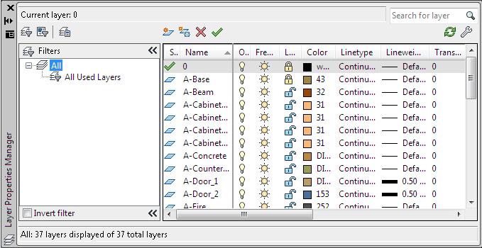
AutoCAD opens the Layer Properties Manager, as shown in Figure 27.
This dialog box lists all current layers and their properties. You can also create new layers and modify current ones.
Drawing Dimensions
Just as the most common objects are lines, the most common dimensions are linear dimensions.
Use linear dimensions for lines, a straight segment of a polyline, or a straight segment in a block. You can also use a linear dimension for arcs and circles—you get the linear length of the arc (not its perimeter length) and the diameter of the circle.
When dimensioning a drawing, create a new layer and label the dimensions so that you can toggle the layer on and off. That way, when you modify your drawing, there will be less clutter on the screen.
To dimension a line, choose Dimension from the menu bar and select linear. AutoCAD responds with the Specify first extension line origin or <select object>: prompt. You can now either pick two extension line origin points or press Enter (or right-click) and select an object for dimensioning. (See Figure 28)
Inserting an External reference [Title Block]
External references (commonly called xrefs) enable you to view any drawing as a reference while in your current drawing. The external drawing is not part of your current drawing. The current drawing keeps track of the location and name of an external reference so you can always reference it easily. As with blocks, you can snap to objects in the external reference, thereby using it as a reference for the drawing process. You can also change the visibility settings of the xref's layers.
To insert external reference:
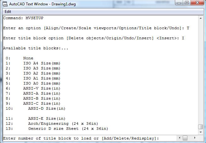
- Type MVSETUP in the command window.
- AutoCAD will prompt: Enable paper space [Y/N]. Select Y.
- AutoCAD will prompt: Enter Option. Select Title Block.
- AutoCAD will prompt: Enter Title Block Option. Select Insert.
- Figure 27 shown below will appear. Type 7 and press Enter to select ANSI A.
- AutoCAD will prompt: Create Drawing. Select Yes.
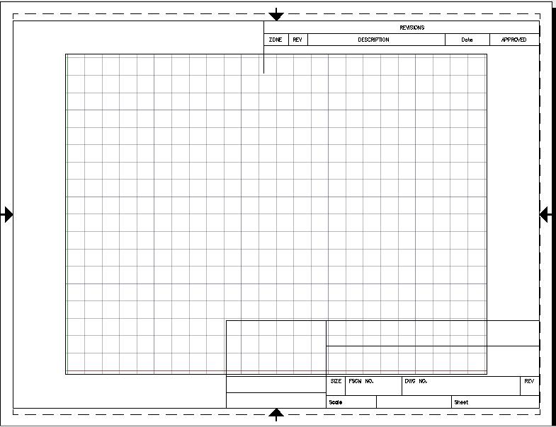
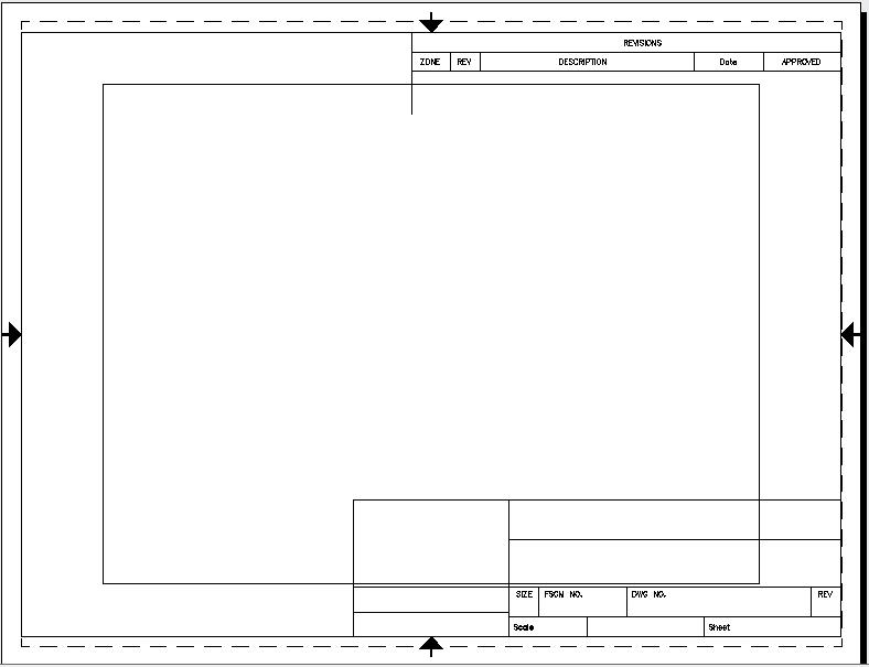
Note: AutoCAD will take you to a new window which shows how the paper will look when it prints. The screen in the middle is known as the viewport (The grid area in Figure 28) and you can move images in and out of this viewport to print desired images. This is very helpful when drawing multiple images in one AutoCAD file but wanting to print only a couple together, or separately. To access the viewport, double click in the center. You can now draw directly in this space or type “pan” and move the background around to find other drawings in the same file.
- The title block acts as a single component. You can select a single line and the entire title block will be selected. You can now scale the title block, move it or make any other changes you wish.
The drawing's scale is set to be 1"=10'. Since there are 12 inches in 1 foot and the scale is set to be 1 inch per 10 feet. You would get 12 x 10 = 120, thus making the Scale for X, Y and Z to be 120. (See Figure 29)
Hatching
To hatch an area, select Draw from the menu bar and select
Hatch icon [ ![]() ] in the Draw group under the Home tab. AutoCAD opens a new tab, Hatch Creation, as shown below in Figure
31.
] in the Draw group under the Home tab. AutoCAD opens a new tab, Hatch Creation, as shown below in Figure
31.
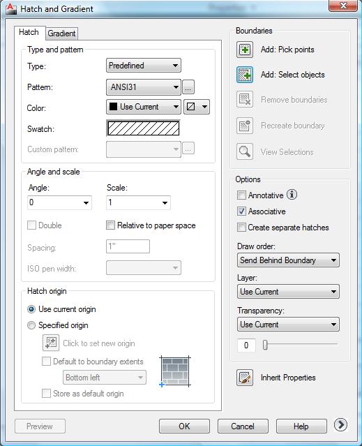
Click on the arrow at the bottom right corner of the Options to open the Hatch and Gradient window.
Use this dialog box to define your hatch. From the Type and Pattern drop-down box, choose one of the three options:
- Predefined: Enables you to select one of AutoCAD's hatch patterns.
- User-defined: Enables you to define your own hatch pattern by specifying the angle and spacing, using the current linetype.
- Custom: Enables you to choose a pattern you have created in your own .pat file.
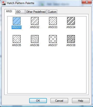
Click the Pattern drop-down box to choose the hatch patterns from a list. (See Figure 32)
In the palette, click the tabs to see the different types of hatches. Click the image tile to choose a hatch pattern and click OK.
Determining Hatching Boundaries
The hardest part of hatching is placing the hatch, not defining it. Hatching an entire object is the simplest way to place a hatch. But often the area you want to hatch is fairly complex, and AutoCAD needs to do some calculations to determine it. The Boundary Hatch dialog box offers two ways to specify the hatch boundary— you can pick points inside an area and let AutoCAD try to find an enclosed boundary, or you can select objects. If you want to hatch an entire object:
- Choose Select Objects. AutoCAD returns you temporarily to your drawing.
- Select all the objects you want to hatch. You can use all the standard object selection options to select objects. Remove and Add are especially helpful.
- Press Enter to end object selection and return to the dialog box.
If the area you want to hatch does not neatly fit into one or more objects, choose Pick Points. At the Select internal point: prompt, pick a point that is inside the boundary that you want to hatch. You can continue to pick internal points to hatch adjoining areas. AutoCAD helpfully highlights the boundaries it finds. Press Enter to return to the dialog box.
AutoCAD Exercise
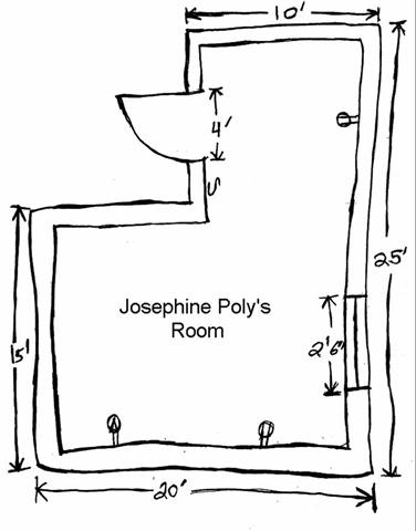
We will be drawing Josephine Poly's room. It will have walls, a window, and a door. It will be dimensioned and have a title block.
Your TA will show you how to use AutoCAD to create the elements you will need to complete this assignment. The scale for the drawing is 1" = 10'.
First insert external reference, refer to page setup. (See Figure 33)
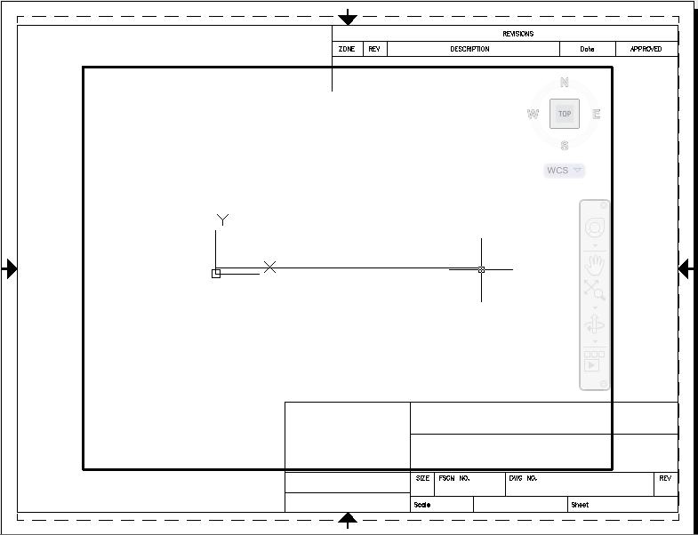
Now it is time to start creating the drawing, so type the word line in the command box. The cursor will then ask you to specify a point on the screen to start the line. To specify a point on the screen, move the cursor to the point that you want to start the line and click the left mouse clicker as shown in Figure 34.
After you have specified the point that you want the line to start now you must specify where you want it to finish. To specify the length of a line type the following: length<angle. For example the base line of drawing is 20' and is a horizontal line, type 20'<0. (See Figure 35)
If the line cannot be seen fully in the viewport, go the View tab then in the Navigate group, click on the arrow next to the third option which should be set by default to Extents. Select Out and zoom out as many times as needed to see the full object.
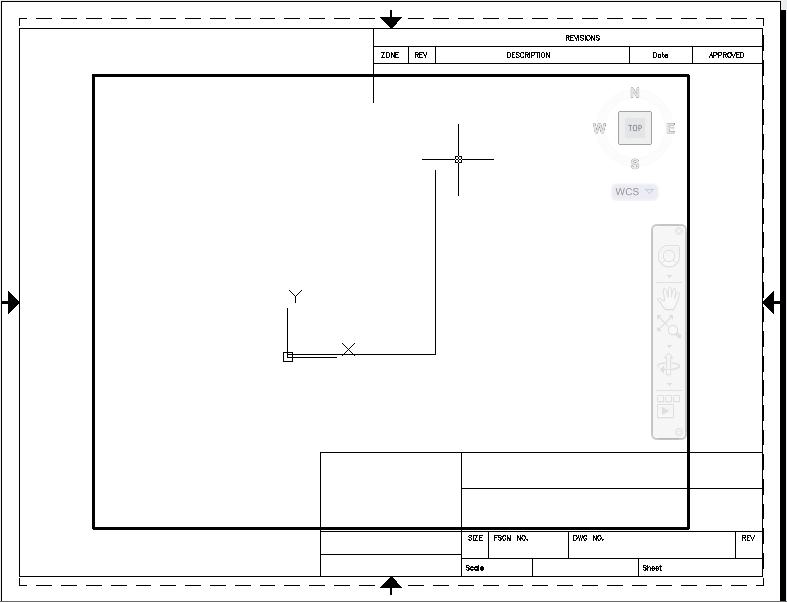
The next line is a vertical line 25' long.
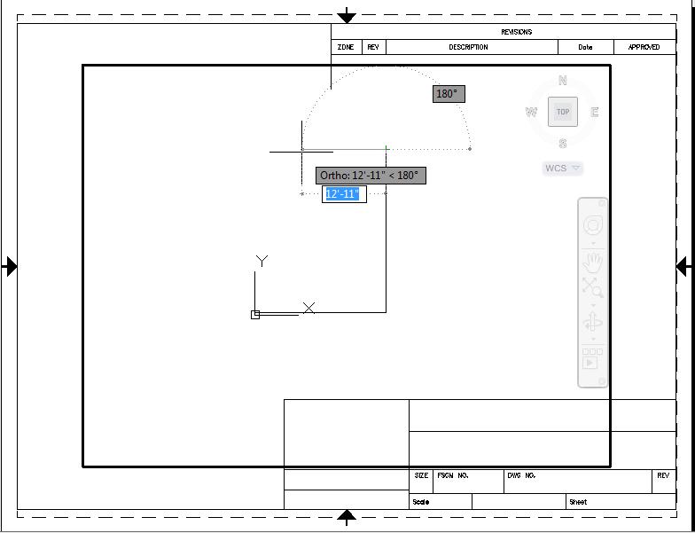
The next line is another horizontal line, to the left. When choosing the angle remember the Angles are in polar form. This means a line to left is 180 degrees.
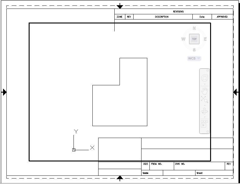
For this particular exercise, you can see that we will only be dealing with right-angles. So in order to simplify matters turn your "ortho" on by clicking on the ortho button situated at the bottom of the screen. Now go ahead and finish drawing the outer-walls. At this point your drawing should look like the following as shown in Figure 37.
Note: When in ortho mode it is not necessary to specify the angle. Just point the line in the direction you wish to go and type in the length then press enter.
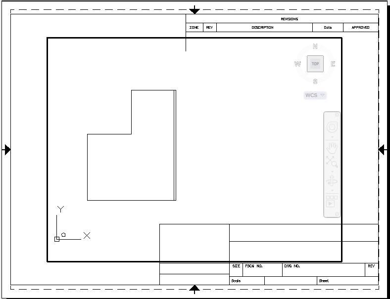
Now we are going to draw the inner-walls. The distance between the inner and outer-walls is required to be 6 inches. To draw a line spaced exactly 6 inches and parallel from another one we will use the "offset" command. Either click the "offset" icon or type offset in the command window. Once you do, the command window will display the following Specify offset distance or [Through] <Through>: prompting you to enter the distance from the original line you wish to create the parallel line. Type the following exactly and press enter: 6" Afterwards, the command window will display Select object to offset or <exit>: basically asking you to select the original line you wish to offset from. Once you select the line you want, AutoCAD will ask you to Specify point on side to offset: which means on which side of the original line you want to create the new line parallel to it; i.e. the left or right of it. For our case let's start on the right most line/outer-wall. The side to which you will "offset" will be to the left of the original line because you want to create the inner-walls. Your drawing should now look like the following Figure 39.
Now that you know how to "offset", go ahead and offset all the outer-walls. When you are done with that you will notice that your drawing has all the inner-walls intersecting one another and in contact with the outer-walls.
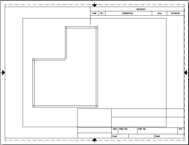
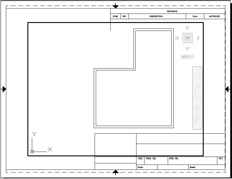
In order to correct this we will use the trim command. For the lines that are intersecting one another we will trim them. Type "trim" or click on the trim icon. AutoCAD will display Select cutting edges… Select objects: select the line you wish to use as the edge along which you will cut another line. Press enter when you select the line you wish to use as your cutting edge. Once you do the command window will display the following Select object to trim or shift-select to extend or [Project/Edge/Undo]: basically asking you to select the portion of the line you wish to trim along your selected cutting edge. The portions we wish to eliminate are the sections of the inner-walls that protrude beyond the 6" boundary and come in contact with the outer-wall. When you "trim" all those sections your drawing should look like the following Figure 41.
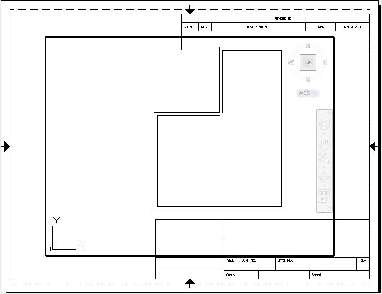
When you are done trimming you will notice that there is a section of the inner-wall that has a gap in it. In order to correct this problem we will use the extend command. Typed "extend" in the command window or click the extend icon. You will receive the message Current settings: Projection=UCS, Edge=None Select boundary edges ... Select objects: which is asking you to select the line to which you wish to extend another one to. So select one of the lines in the gap area and press enter. The message displayed will be Select object to extend or shift-select to trim or [Project/Edge/Undo]: which is asking you to select the object that you wish to extend, however, before you select that line, type "edge" and press enter. AutoCAD will then display the following message Enter an implied edge extension mode [Extend/No extend] <No extend>: and reply to this by typing "extend" and press enter. When you do this AutoCAD will again display the message Select object to extend or shift-select to trim or [Project/Edge/Undo]:, now select the line you wished to extend. Your drawing should now look like the following Figure 42.
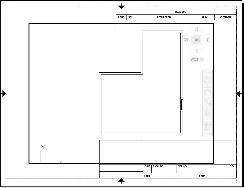
Now let's add a window to Josephine's room. We do this by drawing a 6 inch line from the inner-wall to the outer-wall along the right side of the room. Then we offset that line by 2.5 feet in the appropriate direction. Now turn "osnap" on and make sure that in its settings tab the midpoint option is selected. Once that is done, draw a line from the midpoint of one line to the next. Your drawing should now look like the following Figure 43.
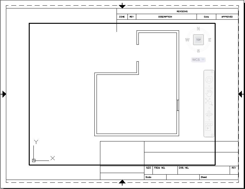
Now let's put a door. On the top-left section of the room draw a 6 inch line from the inner-wall to the outer-wall and offset this line through a distance of 4 feet. Once you do that "trim" the inner and outer-walls situated in-between these two lines. Your drawing should look like the following Figure 44.
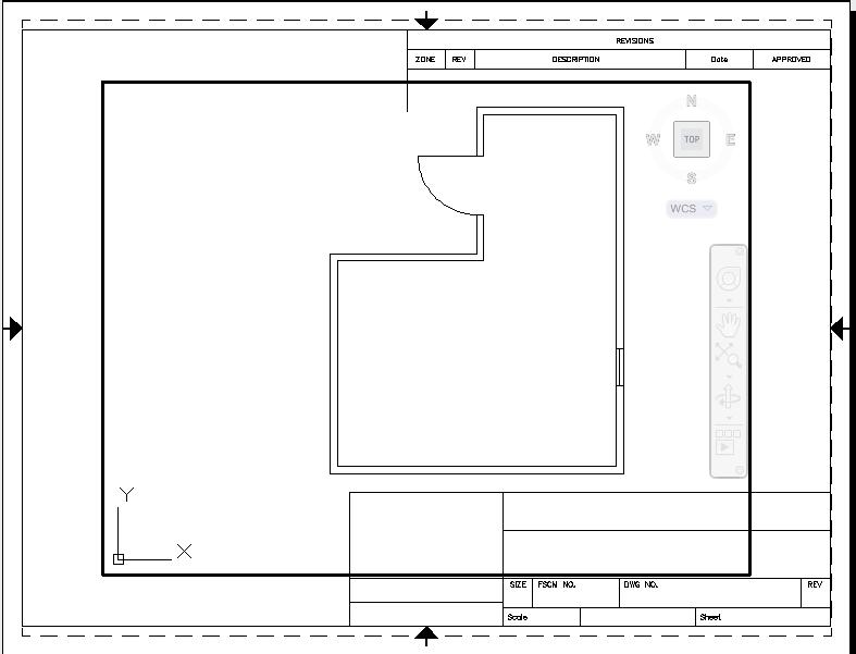
Now draw a line 4 feet in length extending outward from the room from the upper corner of the outer-wall section you just trimmed. Then draw an arc of radius 4 feet from the protruding line to the bottom corner of the outer-wall section you just trimmed. Your drawing should look like the following Figure 45.
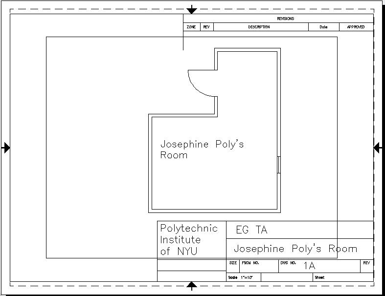
At this point make sure that you have three layers, two will have a predetermined name by AutoCAD (one for your title block and another for command purposes) the second one should be named "Room" for the actual room itself which is what you should have been using to draw your room in. Create a fourth layer called "Text" and a fifth one named "Title block". You will use this layer to label the room as well as the appropriate sections of your title block. Set the "text" layer to current and click on the "Multiline Text" icon and create a text box inside the room. Type the following: Josephine Poly's Room. Then set the current layer to be "title block". In the top left box of the bottom section of the title block enter the company name of "Polytechnic Institute of NYU", in the top right box of the bottom section type the names of your partner and yourself. In the box labeled "scale" input the scale of your drawing which in our case should be " 1"=10' ". Now switch your current layer to the "Text" layer and type, in the box below the one you inserted you and your partners' names, "Josephine Poly's Room" and in the box labeled "DWG. NO." type 1A. Your drawing should now look like the one below in Figure 46:
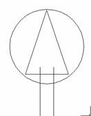
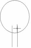
Now create a new layer called "Electrical" and make it current. Create a text box by the door entrance inside the room and type the letter "S" which represents a light switch. Rotate the text box 90 degrees such that it is facing in the same plane that the respective wall exists in (y-axis). Then in the same layer create the following two objects shown below in Figure 47.
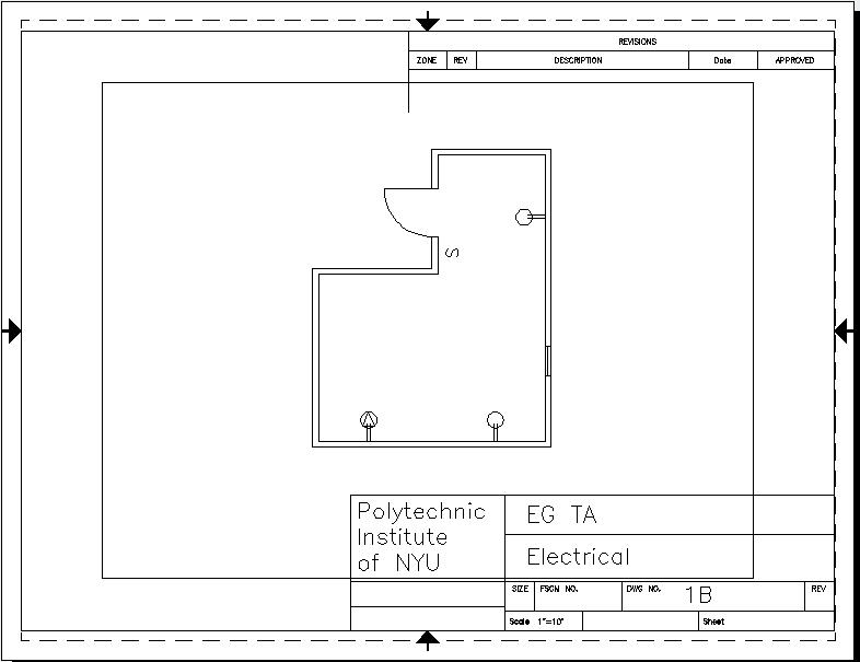
These represent electrical outlets of 220V and 120V respectively. Make them an appropriate size and place one 220V outlet along the bottom wall towards the left side and one 120V outlet towards the right side. Then make a copy of the 120V outlet paste it along the rightmost wall near the top. Make sure that the legs of the above objects are attached to the wall so if the wall is moved the outlets will come with it. To do this, you can use the rotation command, if necessary. Now turn the text layer off and type "Electrical" where you had previously typed "Josephine Poly's Room" and in the box labeled "DWG. NO." type 1B. Your drawing should now look similar to the one below in Figure 48.
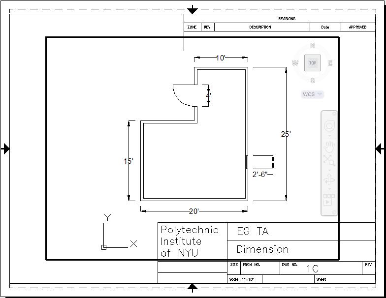
Now create a new layer called "Dimension", set it to current, and turn the electrical layer off. Type "Dimension" where you had previously typed "Electrical" and in the box labeled "DWG. NO." type 1C. Create linear dimensions for all the outer-walls except for the one with the door. Then create one for the window and door. Your drawing should now look similar to the one below in Figure 49.
Now you are done. Congratulations.
Printing
In order to print the drawings, have the drawing set to as you would like it printed. For example, if you would like to only have the dimensions printed, have the dimensions layer on and the others off. Have all the layers turned on before printing.
Go to the top bar of AutoCAD.
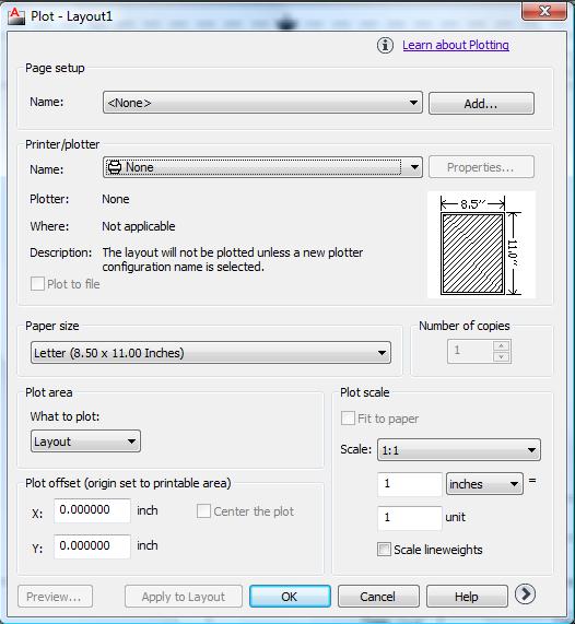
Click on the last icon that looks like a printer. This is the plot icon. A plot dialog window will appear as shown in Figure 50. Make sure the proper printer is selected in the Plot Device tab. See Figure 50.
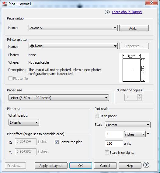
Next, select the Plot Settings and change the Plot Scale to custom and then specify underneath: 1 inches = 120 drawing units. Check off Center the Plot in the Plot Offset section. And last but not least, select Extents in the Plot Area. Everything should look like Figure 51. You may preview your drawing print out by click on Preview. When satisfied with the entire options click OK.
You have now completed the lab. Log off the PC and make sure your work area is clean, with any scrap paper you used, etc. properly of.
