3D Printing Guide
Mandatory 3D Printing for all SLDPs
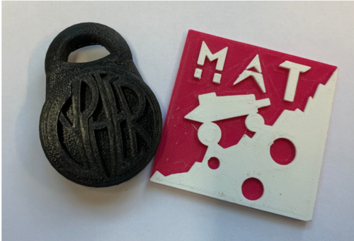
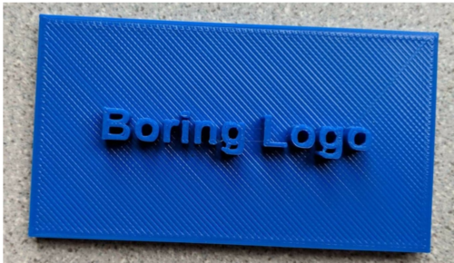
All SLDP groups, except RAD groups, will be required to design and 3D print a one-color logo. All specifications outlined in the Logo specification section must be met. If a group designs and 3D prints a course modification or robot part for extra credit, they will be excused from the mandatory one-color logo 3D print. All groups may design and print a two-color logo to meet the mandatory 3D printing requirement and will receive extra credit for using two colors. Deadlines for this mandatory print are outlined in the deadlines section below.
Groups must submit a .STL file of a logo through the 3D Printing Submission portal by Benchmark A and receive approval from a ProtoLab TA by Benchmark B.The printed logo is a requirement for commissioning, and failure to do so will result in point penalties on the project grade.
ProtoLab Schedule
- Monday: 2 PM to 6 PM
- Tuesday through Friday: 12 PM to 6 PM
3D Printing Extra Credit
For HIR groups, 3D printing extra credit is awarded for 3D printing one-floor plan of the exterior of your building. Submit an STL file of a single floor plan through the 3D Printing Submission portal and receive approval from a ProtoLab TA to get it printed before Commissioning.
Logos Specifications
- Maximum material weight does not exceed 15 g total
- Can be one or two colors
- One-color logos are mandatory for all SLDP groups
- Two-color logos are extra credit for all SLDP groups
- Two STL files are required for two-color logos, submitted as a .zip file on the website
- Logos must be integrated with your project in some way
- Must be original content
- Cannot be exclusively text or a simple geometric shape
Must be exported as a .STL with correct scaling (make sure the document units are set to mm before exporting)
Software
To design your logo you will need any CAD software as well as Cura. There are many options for software that can be used, the only necessary feature is that the software can export files as an .STL (stereolithography) extension. Some examples of recommended software:
- Autodesk Fusion 360 – Free student edition
- Autodesk Inventor – Free student edition
- 123D – Free (Online)
- TinkerCAD – Free (Online)
- Blender – Free (Open source)
- OpenSCAD – Free (Open source)
- Solidworks – Available in NYU computer labs
- Rhinoceros – Free evaluation available for MacOS
To make a 2 color design you will need to save your logo in two separate .STL files (one for each color) and submit both as a .zip file to the website. The two files are then imported into CURA and aligned, with separate extruders selected for each color.
Design Considerations
- Make a flat bottom: A large flat bottom increases the adhesion between the build platform and the part, keeping the part from shifting around during a print.
- Keep overhangs close to 45 degrees: Each layer of a 3D print needs to be supported from below. You can avoid adding additional supports to a print if all the overhanging parts are at no more than a 45-degree angle from vertical.
- Avoid thin walls and thin columns: Thin walls and columns often do not come out well. The thickness of a thin wall should be a multiple of 0.35 mm. Thin columns will usually come out distorted because they melt under the nozzle.
Advanced Prints
For any group considering an advanced print through the MakerSpace:
- One person in the group must have completed the training on the machine prior to making the request.
- Groups must fill out the MakerSpace/EG1004 Print Request form and get approval from a ProtoLab TA before going to the MakerSpace to complete the print.
- For approval, you must present the file that you wish to print as well as making sure the specifications of the print line up with what was entered on the form.
- After filling out the form, you will have a week to complete the purchase otherwise it will be voided.
Submission and General Guidelines
- Submission of your 3D designed parts will take place through the EG website using the “3D Printing Submission” tab of the left menu. DO NOT USE THE NORMAL SUBMISSION TAB. Your submissions must be .STL files or .zip files.
- If your logo has two colors, you must compress your two STL files into a .zip file for submission.
- Make sure to submit an STL with the correct scaling.
- If you choose to build your model in inches, remember to convert to millimeters before saving the STL
- After your submission has been received, stop by the Modelshop to work with a ProtoLab TA at your earliest convenience. This process is necessary for your files to be approved and printed.
- Once your design has been approved, you can choose to print it at the EG ProtoLab or self-print it at the MakerSpace. However, if you choose to self-print, it must be first approved by a ProtoLab TA, and the final printed part must be shown to a ProtoLab TA to receive extra credit.
- When you pick up your print, you will receive a “Proof of Approval” that recognizes the validity of your print. Please keep the slip with your printed part at all times - you will not be allowed to use the printed part unless the slip is present.
- As you are submitting your 3D designs for your logos, course modifications, or robot parts, please keep in mind the requirements posted on the EG Manual. If you have any further questions, please stop by the Modelshop and inquire a ProtoLab TA.
Deadlines
- Initial STL file submission for mandatory prints is due by Benchmark A (Week 7)
- The 3D printing process can take multiple revisions, you are required to submit the first attempt by Benchmark A, but you will be allowed to make any modifications until the final deadline of Benchmark B.
- STL file approval for prints is due by Benchmark B (Week 10)
- You must meet with a Protolab TA during Protolab hours to get your print approved. You cannot get your print approved without meeting with a Protolab TA. Your print will not be processed if it is not approved.
- If you miss the Benchmark B deadline, subsequent submissions will not be considered. All submissions must be approved by this deadline (with very limited exceptions).
- Printed part by Commissioning Deadline (Week 14)
- You must have picked up your printed part by commissioning.
- These deadlines are applicable to mandatory logo prints, extra credit prints fulfilling the mandatory logo print requirement, and all SLDPs extra credit prints.
Cura
Cura is a critical piece of software for our 3D Printers. STL files do not contain the instructions the printer needs to position the extruder; to do this Cura “Slices” the model. This process analyses the 3D models that have been imported and slices them into individual layers that the printer can lay down. The software also determines which extruder to use, which, in turn, decides the color of the filament used.
Toolbar
The toolbar on the left side of Cura allows files to be imported and some final adjustments on the object before slicing. There are 9 functions available:
- Open File: Loads the model onto the buildplate
- Move: Translate the model in the X, Y, and Z directions (in millimeters)
- Scale: Scale the model in the X, Y, and Z dimensions (in millimeters). Can also scale by a percentage. Uniform scaling will ensure that the object stays in the correct proportions. Can reset the object to its original position (Reset).
- Rotate: Rotate the model in the X, Y, and Z dimensions (in degrees) by dragging rings around the object.With ‘Snap Rotation’ selected the rotation will occur in 15 degree chunks. Can also automatically adjust to place the nearest flat edge onto the platform (Lay Flat). Can reset the object to its original position (Reset).
- Mirror: Can mirror the object with respect to each axis. There are six arrowheads, two for every axis, and clicking on the arrow will mirror the object in the desired direction.
- Per Model Settings: Can allow specific settings to be applied to different models on the build plate
- Print Selected Model with Extruder 1/Extruder 2: With each option, select the desired extruder for each part of the model.
- View Mode: There are three different viewing options - Solid, X-ray, and Layers
- Solid: Selected by default and represents the model as it was digitally created
- X-ray: Allows to look through the model and detect any possible missing or erroneous internal geometry.
- Layers: Represents the print moves of the nozzles only available after the part has been sliced/prepared
Part placement onto the build plate is a crucial step in preparing a Cura print file. One of the most common reasons for print failure is a poorly oriented part. The key is to minimize the overhanging elements of the model.
Importing Files
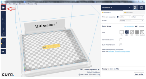
To create a multicolor print, at least two STL files must be imported, each file will use one extruder. To import the first file, click the “Open file” button on the top left.
Select one of the two files that is used in the design; it should load into the build-plate window. Next add the second file with the same method.
Selecting Colors
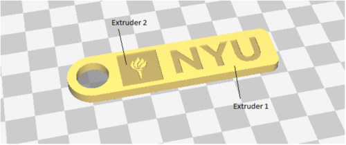
Because the Ultimaker 3 is a dual-extrusion printer, it allows prints to have two colors, but it is important to choose the correct corresponding extruder to allow the print to have the correct color on its parts. By default, parts with extruder 1 will appear as a light yellow color while printing with PLA, and extruder 2’s parts will appear as a darker yellow. To assign the extruder to a specific part of the print, first select the part, then choose extruder 1 or 2 on the left sidebar.
Figure above shows how parts will appear as different colors when selected under the two extruders.
Printing Settings
Once everything is placed correctly and extruders have been selected, it is then necessary to ensure the ideal print settings are chosen. On the right side, there is the settings panel where different settings can be chosen for each extruder. Since only PLA material will be used, make sure to choose both “AA 0.4” and “PLA” options under “Print core & Material.” Next, under “Profile” are a set of pre-created settings from CURA:
- Fast print (0.2 mm): Makes a quick print but with lower quality
.
- Normal (0.15 mm): Decent quality print with an acceptable print time. This profile is applicable to most prints.
- Fine (0.1 mm): Good quality print.
- Extra Fine (0.06 mm): Prints with a very smooth surface quality.
Most of the time, the print will be completed with the Normal profile. Under “Print Setup,” there is a toggle for “Recommended” versus “Custom.” Custom settings allow for more in depth adjustments, whereas recommended settings have the few necessary settings for overall adjustment. Below explains the settings more in depth:
- Infill: the amount of infill wished to have in the print. Avoid printing solid parts (100% infill) unless ABSOLUTELY necessary. The denser it is, the longer it will take. 20% is sufficient for most prints.
- Generate Support: If there are any parts of the print that has overhanging parts, selecting this option will allow a support structure to be generated below it. This structure can be removed after the print is finished.
- Support Extruder: Choose the extruder that will print the support structure; usually it should be the same extruder as that part of the print.
- Build Plate Adhesion: This option adds a brim or raft around the base of the model to ensure that the print sticks to the build plate. Especially important to have this feature active for smaller parts.
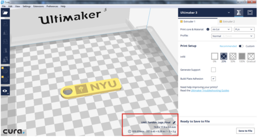
After the model has been sliced (prepared for printing), selecting “Layers” under “View” will show a layer-by-layer preview of the print. On the lower right corner, you have the option to edit the name of your file, view the dimensions of your print, as well as the estimated print time and filament usage. If the print exceeds the required dimensions or material use, it should be rescaled or redesigned until it meets the requirements.)
To view print time and material use
Once the material usage has been confirmed and the correct settings have been chosen, click “Save to File” and a .gcode file will be generated for printing. If a USB is inserted this will read “Save to Removable Drive”. Note that once a print has been sliced and saved as a .gcode file, it cannot be changed and the settings can not be viewed. Settings can only be adjusted with a .stl file. If you wish to save the current settings, make sure to go to “File” > “Save Project.”
Common Problems
If two parts cannot be merged or placed together-
- Cura, by default, drops the objects on to the build-plate and keeps objects apart. The following steps are needed to combine the filler rectangle within the keychain:
- Under “Preferences”, select “Configure Cura”
- Under “Viewport behavior,” make sure to deselect both “Ensure models are kept apart” and “Automatically drop models to the build plate” if they are not already deselected
- Save your preferences
- Return to the buildplate and make sure both objects are lying flat on the build-plate by using “Rotate” => “Lay Flat”
If Lay flat option places the object on an angle-
- It is very important to make sure that the print is flat on the build plate. However, sometimes due to the way that the model was built, the Lay Flat option won’t be able to correctly orient the object
- To fix this problem, you can:
- Adjust it by eye with the rotate tool
- Make sure the Z value is 0 mm under “Move”
- By holding down the right key on a mouse and dragging, you can access whether the print is flat on the build plate.
