3D Printing and Emblem Guide
ProtoLab Schedule
All standard 3D Prints must be submitted, approved, and printed through ProtoLab unless given special permission by a ProtoLab TA, the Prototyping Committee, or a professor.
- Monday: 2 PM to 6 PM
- Tuesday through Friday: 12 PM to 6 PM
Mandatory 3D Printing for all SLDPs
All SLDP groups will be required to design and 3D print a one-color logo. All specifications outlined in the Logo specification section must be met. All SLDP groups may design and print a multicolor logo to meet the mandatory 3D printing requirement.
Deadlines for this mandatory print vary by section. Generally, the timeline is as follows:
- Groups must submit a .STL file and a .3MF file of the logo through the 3D Printing Submission portal by Benchmark A.
- A Protolab TA will review the print and provide feedback if necessary. Approval from a ProtoLab TA must be received by Benchmark B.
- The logo must be printedby Commissioning.
Note that while Protolab is the recommended resource for our students, prints made outside of Protolab will be reviewed on a case-by-case basis and must be approved by a Protolab TA. This policy applies to prints made using other NYU facilities (such as the MakerSpace) or elsewhere (such as using a personal printer).
Failure to complete this print by the deadline will result in point penalties on the SLDP grade.
Mandatory Manufacturing for all RAD Projects
All RAD groups will be required to implement one manufacturing method in the creation of their prototype. Manufacturing methods include 3D Printing, Laser Cutting, CNC Milling, Advanced Printers, Sewing, and Wood Working. For all methods, training with the MakerSpace is required, go to their training website for the associated instructions to receive training a specific method.
Advanced Prints
For any group considering an advanced print through the MakerSpace:
- One person in the group must have completed the training on the machine prior to making the request.
- Fill out the MakerSpace/EG1004 Print Request form and get approval from a ProtoLab TA before going to the MakerSpace to complete the print.
- For approval, present the file that you wish to print as well as making sure the specifications of the print line up with what was entered on the form.
- After filling out the form, the team has a week to complete the purchase otherwise it will be voided.
3D Printing Specifications
All prints:
- Maximum Duration 8 hours; prints that exceed this limit will be assessed for feasibility with a different manufacturing method
- All submissions require a minimum of one .STL file and one .3MF file contained in a .ZIP folder. Submissions missing either file type will automatically be denied
- Original Design & Content
- Must be different from other groups’ submissions
- Must not include figures or models from other sources or .STLs generated using image converter softwares
- Must be complex; will be judged by ProtoLab TAs and the Prototyping Committee
Logos:
- Must represent project appropriately
- Maximum material weight does not exceed 15 g total
- Can be one or more colors
- One-color logos are mandatory for all SLDP groups
- A group can make a logo using up to four colors if they wish
- Submission of one .STL files and one .3MF file that is arranged, scaled, and color properly for a multi color part
- Logos must be incorporated into the SLDP (i.e. attached to a physical part of the model)
- Must be original content
- Cannot be exclusively text or a simple geometric shape
- Correct file types must be submitted to 3D printing submission tab
- Must be exported as .STL and .3MF from Bambu Studio with correct scaling (make sure the document units are set to mm before exporting)
RAD, HIR Parts:
- Maximum Size 10 x 10 x 10 in, Maximum Weight per part 300 grams
- Note: All parts of a print must fit on one build plate. A print requiring more than one build plate will be denied.
- All prints that are past 3 x 3 x 3 in will be evaluated for if a different manufacturing method can be used or if the design could be changed
- All parts that are past 5 x 5 x 5 in and are resubmitted due to a design change cannot be printed more than twice
- Printed parts can be assembled using any method post print, as long as there is no excessive waste of material.
- Printed parts used for VEX course modifications are not permitted for use
Only LARGE HIR build parts (LEED Accreditation parts, mobility features like stairs and elevators) will be accepted. Small, decorative parts (shrubbery, chairs, bike racks) will be denied and these pieces must be made in a different way.
Submission and General Guidelines
- Submission of your 3D designed parts will take place through the EG website using the “3D Printing Submission” tab of the left menu. DO NOT USE THE NORMAL SUBMISSION TAB. Submit your Bambu .STL and/or .3MF files in a .ZIP file to the website.
- Make sure to submit a .STL and/or .3MF with the correct scaling.
- Name the files with the correct name as referred to the Bambu Studio Guide. Please make sure the colors selected in Bambu match the parts of the body you would like printed in that color.
- After a submission has been received, meet with a Proto TA in person to have the print approved during ProtoLab hours.
- An SLDP team has the option to self-print its design (if it is NOT a Logo) at the MakerSpace. SLDP teams should submit non-logo prints to the website to have ProtoLab print the design.
- To view the status of a print submission, go to the 3D printing Submission tab.
- Pending means the print is in the process of being approved.
- Approved means the print is in the queue to be printed
- Denied means the design needs changes and must be resubmitted.
- Currently Printing means that the part is being printed.
- Successfully Printed means the print is finished.
- Dropped Off means the print has been dropped off at the cubbies in the Open Lab, and are ready to be picked up.
- An email will be sent by a ProtoLab TA to SLDP groups when logos are denied or delivered.
- Before submitting 3D designs for logos, robot parts, or HIR building partsSLDP parts, please keep in mind the requirements posted on the EG Manual. For questions, visit a ProtoLab TA during ProtoLab hours.
- RAD: ProtoLab TAs will have the final decision over whether or not a part should be 3D printed or manufactured using another method. Also, while some parts submitted for 3D printing may be taken from preexisting designs online, your end result should still be an original design in order to not violate NYU’s academic honesty guidelines.
Deadlines
- Initial STL file submission for mandatory prints is due by Benchmark A
- The 3D printing process can take multiple revisions, you are required to submit the first attempt by Benchmark A, but you will be allowed to make any modifications until the final deadline of Benchmark B.
- STL file approval for prints is due by Benchmark B
- You must meet with a Protolab TA during Protolab hours to get your print approved. You cannot get your print approved without meeting with a Protolab TA. Your print will not be processed if it is not approved.
- If you miss the Benchmark B deadline, subsequent submissions will not be considered. All submissions must be approved by this deadline (with very limited exceptions).
- Printed part by Commissioning Deadline
- You must have picked up your printed part by commissioning.
- All non-mandatory prints must be submitted & approved at least one week prior to Commissioning deadline
- All prints approved before this deadline will be printed. If ProtoLab fails to deliver on an approved print request, please consult RAD mentor/recitation professor on adjusting project deliverables/expectations.
- All prints submitted/approved after this deadline are not guaranteed to be fulfilled. Project deliverables/expectations cannot be negotiated due to unfulfilled print requests after this deadline. Plan accordingly.
Design Considerations
A logo is a design that should be a marker of the company, something that identifies your group. There are many different ways to go about designing a logo, and there are many different types of logos, as well. Some examples include:
- Combination
- This is a logo that has a combination of a picture representing the company, as well as the company name. The name can be stacked on top or below the picture, or embedded within it. It’s a great way to have your company’s name associated with an image, especially for a company that is just starting up.
- Examples: Taco Bell, Dunkin’ Donuts, NBC
- This is a logo that has a combination of a picture representing the company, as well as the company name. The name can be stacked on top or below the picture, or embedded within it. It’s a great way to have your company’s name associated with an image, especially for a company that is just starting up.
- Emblem
- An emblem is a type of logo where a wordmark, letterform, or pictorial symbol are housed within a distinct shape that is part of the design. They are another example of a logo with many elements that can allow for your company’s name to stand out with its distinctive design.
- Examples: Harley Davidson, BMW, Converse
- An emblem is a type of logo where a wordmark, letterform, or pictorial symbol are housed within a distinct shape that is part of the design. They are another example of a logo with many elements that can allow for your company’s name to stand out with its distinctive design.
- 3D Logos
- 3D Logos make use of contours and shading to depict a 3D design, usually along with a lettermark. Brands can use a 3D logo to evoke a sense of futurism and technology.
- Examples: Royal Academy of Engineering, Rosetta Stone, Renault
- 3D Logos make use of contours and shading to depict a 3D design, usually along with a lettermark. Brands can use a 3D logo to evoke a sense of futurism and technology.
All of these logo types are great ways to familiarize yourself with not just logo design, but using CAD software to sketch out designs, as well.
Besides the design of the logo itself, since these logos will be 3D printed, one must also consider the real life parameters of 3D printing. Here are some general guidelines to make sure that your carefully designed logo will not fail when printing:
- Optimize 3D print-bed adhesion
- A large surface area against the build plate will maximize the adhesion between the build platform and the part, which keeps the part from shifting around during a print.
- Keep overhangs close to 45 degrees
- Each layer of a 3D print needs to be supported from below.
- You can avoid adding additional supports to a print if all the overhanging parts are at no more than a 45-degree angle from vertical. This allows for a shorter print time, as well as less filament used.
- Avoid thin walls and thin columns
- Thin walls and columns often cause a print to fail.
- The thickness of a thin wall should be a multiple of 0.20 mm.
- Thin columns will usually come out distorted because they melt under the nozzle, and the layer might separate from the rest of the print.
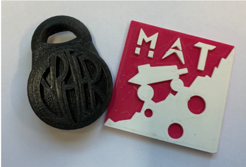
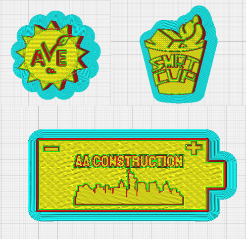
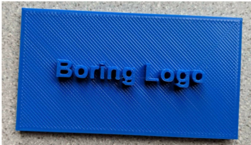
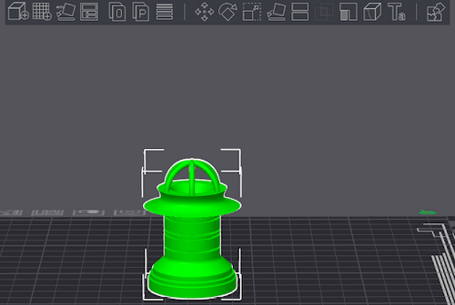
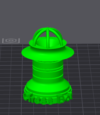
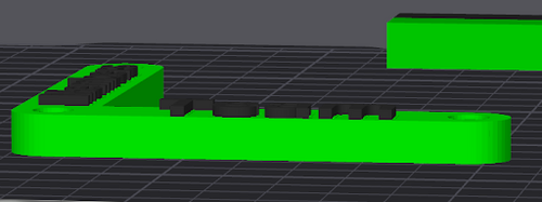
Below are some examples of logo prints that were approved and successfully printed (Fig. 4 & 5) as well as an example of a bad logo (Fig. 6):
Software
To design the SLDP logo, any CAD software and Bambu Studio are required. There are many options for CAD software that can be used, the only necessary feature is that the software can export files as a .STL (stereolithography) extension.
Note: There may be limitations troubleshooting software other than Fusion 360 as TAs are mainly trained in Fusion.
To make a 2+ color design you will need to save your logo in two separate .STL files in your CAD software (one for each color). The two files are then imported into Bambu Studio and aligned, or cut one body in Bambu Studio and assign separate colors, and then submitted to the website as a .3MF or .STL. Please refer to the Multicolor Methods section in the Bambu studio guide section for further help on printing with multiple colors.
Bambu Studio Guide
Bambu Studio is a critical piece of software for our 3D Printers. STL/3MF files do not contain the instructions the printer needs to position the extruder; to do this, Bambu Studio “slices” the model into smaller layers. These layers are then converted to commands to move the machine called G-Code toolpath. The software is also used to set the proper color of filament used for each object. The Protolab TA can then load each extruder with the desired filament color and type.
Initial Setup
- Download Bambu Studio: Bambu Studio Download Link
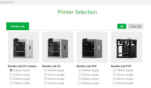
- After downloading the software with the link above you will be prompted to select the region then asked to select the printers you’d like to have added to your library.
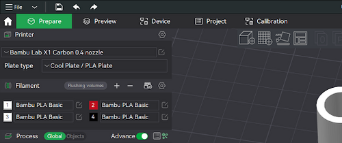
- Ensure that the Bambu Lab X1 Carbon with the 0.4 mm nozzle is the only box selected. If you do not select this printer your print will be denied by a Protolab TA. This is the only printer that is available in the Open Lab / Modelshop.
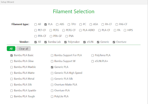
- After clicking “Next”, you will be presented with different filament types that can be used in the software. The Protolab only has PLA, so no other box should be checked. Ensure that your window matches Figure 2, above.
- After this you will be ready to start slicing your file. It will prompt you to create an account with Bambu Studio, however you do not need to create an account to use the software.
Toolbar
The toolbar near the top of Bambu Studio allows files to be adjusted on the plate before slicing. Please note that images might appear differently if Dark Mode is not enabled (See the appendix at the end of this document for how to enable Dark Mode).
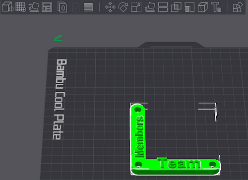
Functions as listed from left to right in Fig. 3:
- Add: Object [Allows you to import another object on the plate]
- Add: Build Plate [Allows you to add another build plate if desired]*
- Auto: Orientation [Automatically places the object in a particular orientation]*
- Auto: Arrange [Automatically arranges object on the build plate]
- Split into objects [Splits model typically when using Text Tool]
- Split into parts [Splits model when using the Assemble Tool]
- Variable layer height [Creates different layer heights for faster printing]*
"*" These tools will most likely not be useful for your print, but are available options
Functions as listed from left to right in Fig. 4:
- Move: Translates the model in the X, Y, and Z directions
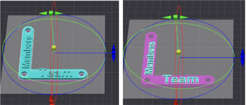
- Rotate: Rotates the model about a selected internal axis by dragging the rings around the object.
- Scale: Scales the model in the X, Y, and Z dimensions in mm or by a percentage.
- Uniform scaling: Preserves the objects original proportions
- To scale an individual dimension (ie thickness in the z direction), turn off uniform scaling
- Lay on Face: Adjusts the nearest flat edge of the object onto the platform.
- Cut [Cuts the object in to the amount of parts desired and the location selected]
- Mesh Boolean**
- Support Painting**
- Seam Painting**
- Text Shape**
- Color Painting**
- Assembly View [Allows you to view the model fully assembled]
"**" These tools will most likely not be useful for your print, but are available options
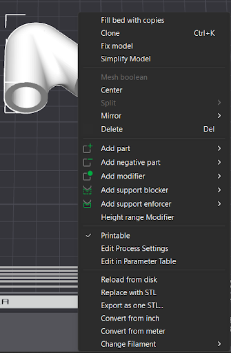
By selecting on the part and then right clicking, you are presented with the following useful options:
- Clone: make multiple copies of the part
- Fix Model: fixes the model in the current place
- Center: Moves the model to the center of the build plate
Part placement onto the build plate is a crucial step in preparing a Bambu Studio print file. One of the most common reasons for print failure is a poorly oriented part. The key is to minimize the overhanging elements of the model and ensure the part is printed on the most stable face.
Importing Files
To create single parts, simply:
- Navigate to the top left and click the file icon
- Select import,
- Pick the file you want to import from your computer.
Note the file must be of the following type: STL, STEP, 3MF, STP, SVG, AMF, or OBJ.
3D printing is a form of Fused Deposition Modeling (FDM)): individual layers of filament are deposited and fuse together. “Slicing” is the process of taking a 3D object and dividing it into these individual layers to generate a set of instructions for the printer’s extruder to follow, known as a “toolpath.” These toolpaths are stored as g-code files.
Adding Text
There are very simple ways to add text to your logo. The Bambu Studio software allows you to generate text on certain faces of your object.
- Navigate to the “Ta” Section of the Toolbar
- Fill out the desired text in the “Input Text” section
- Select the face where you would like the text to appear
- Adjust settings to achieve the desired look:
- Font: Adjusts the font type of the text
- Size: Adjusts the total size of the text
- Thickness: Adjusts the thickness of of the text
- Text Gap: Adjusts the space between the letters of the text
- Angle: Adjusts the angle at which the text aligns with
- Embedded depth: Adjusts how deep into the part the text is located
- Surface: Adjusts if the text is connected to a surface or free to move about
- Horizontal text: Moves the test to a perfectly straight line.
Multicolor Part Method 1
There are 2 ways to create a multicolor part. This method requires a bit more work in the CAD software before importing the part. You must import at least two STL files. This method is the easiest if you already have an assembly of objects in your CAD software previous to importing. If you only have 1 object try method 2.
- To import the first file, click the “File” icon on the top left of your window.
- Select both files, it will load them both onto the build plate.
- Navigate to the “Stacking/Assembling Parts” or the “Selecting Colors” section for the next steps.
Multicolor Part Method 2
This method requires a bit more work in the slicing software after placing the part on the build plate. Here you must have only 1 STL file. This method is easiest if you aren’t a big fan of CAD.
- Navigate to the “Cut” tool in the Toolbar (Hamburger icon
- Click and drag the gray box to the height of the separation. The blue and purple sections represent the 2 parts after the cut
- Hit “Preform cut” and your parts will be separate. To confirm navigate to the objects tab to view the 2 parts you have created.
- Navigate to the“Selecting Colors” or “Stacking/Assembling Parts” section for the next steps.
Selecting Colors
The reason that you are able to print multiple colors is because of the Bambu Labs AMS (Automatic Material System). The AMS is a filament management system responsible for unloading and loading new filament to be used in the same file. By selecting the correct color you send a signal to the AMS to change the filament to a new color. The Bambu Labs X1-Carbon is a single extruder 3D printer which means that if you do not select the proper filament change then the resulting object will be a singular color. By default you will only be able to see only 1 type of filament with the color indicated on the left with the number 1,2,3, or 4. In order to use multiple colors you must…
- Select the “+” icon and add more filament colors and types
- Ensure that the material is labeled “Bambu PLA Basic”
- To change the desired color appearance click on the number to the left of the material type and select the desired color. This will change the appearance of the part in the software.
Stacking/Assembling Parts
For 2 colored parts you must stack the parts on top of each other so they are connected. To connect the parts you use the assemble tool.
- Hold “ctrl” and click your parts.
- Right click and select assemble. To ensure you created the assembly go to the objects tab.
- From their click on the part that you wish to move on top.
- Use the “Move” tool to move the part so that it is not flying above to the part below it. Your part should look like this when done.
- Export the file as a “Generic 3MF” file by hitting the “File” icon then “Export” then “Export Generic 3MF”. If you do not do this then when sending the file to us we will only see the 1 color with the wrong orientation.
Printing Process
After placing the objects correctly with the proper color selection, the final step is to ensure all the correct print settings are selected. Here are the settings from top to bottom.
- Printer section:
- Bambu Lab X1 Carbon 0.4 nozzle
- Plate type:
- Cool Plate / PLA Plate
- All Filament:
- Bambu PLA Basic
- Process:
- For normal quality: 0.2mm Standard
- For high quality: 0.16mm High Quality
- For strength: 0.2mm Strength
You should select the “Standard” profile for the “everyday” normal prints that will not experience heavy loading or stresses. You should select the “High Quality” profile for prints that require a lot of precision like smaller objects. You should select the “Strength” profile for prints that will experience stress and torque (this will increase the infill density of the part).
Sending Printing Request
To send the part to a proto TA you must
- Go to the “File” icon in the top left
- Hit Export
- Depending on the amount of colors
- FOR ONE COLOR PARTS: Hit Export all objects as one STL/3MF
- FOR TWO COLOR PARTS: Hit Export Generic 3MF
Use the following naming convention: Part_Type_Section_Date
Ex: Gyro_holder_Strength_A2_1-31-24
Part = Part Name
Type = Standard, High Quality, Strength
Section = EG Section
Date = 1-31-24
Upload it to the EG Website in a Zipped Folder
Do not slice the part at all! The reason we ask not to slice your part is because we can determine the fastest way to print your file with the correct settings. You are encouraged to talk to a proto TA with any questions about printing. A proto TA still has the ability to deny the request to print your part but will always provide you a reason why your part was denied. A proto TA will deny your part for the following reasons:
General Parts:
- Incorrect file type (STL/ 3MF)
- Incorrect naming convention
- Would be better manufactured in other method
- Parts are not on the build plate or connected to a part on the build plate.
Logos:
- Incorrect file type (STL/ 3MF)
- Incorrect naming convention
- A basic design
- Possible plagiarized (Will ask for justification)
If you are curious about the process for creating a toolpath and slicing a model, consult the Appendix.
Common Problems
If you are having problems with your part or CAD file consult an Protolab TA so they can assist you in properly sending your file.
Appendix
Enabling Dark Mode
If you are like us then you enjoy dark mode on all of your programs. In order to activate dark mode,
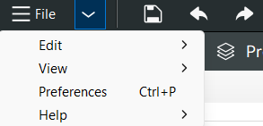
- Hit the Dropdown Arrow and click “Preferences”
- Scroll down and check the box for “Dark Mode”.
Supports
There are multiple different types of supports to help assist the printer create geometry with overhangs. Overhangs are sections of objects that extend outward and do not have direct support.
There are 2 types of support structures that are available in Bambu Studio:
- Normal: Creates box like structures with a small infill density so you are able to break off that section off the print after it is completed. This process uses more filament but is more reliable in terms of print success.
- Tree: Creates cylinder like structures with variable layers and heights. They are thin branch structures so you are able to easily break off after printing. This process uses less filament but is less reliable in terms of print success.
It is best to select the “Auto” function over the “Manual” function to ensure better success. After selecting the support type you can navigate to the Preview tab to view all the supports that are generated.
Slicing Part + Data
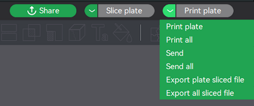
To slice the part, navigate to the top right of your window where you convert the final model into g-code for the machine to print. In order to convert your file into a printable path click the “Export plate sliced file”. This file you will export and put onto the SD card to be able to print.
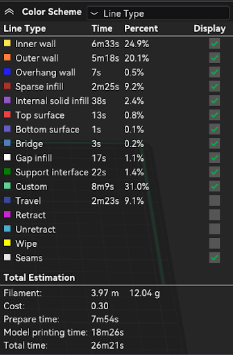
After the model has been sliced, you can navigate to the preview tab and you will see a color coded chart similar to the one shown here.
This menu displays a lot of information. The key features to note are the support interface, seams, and outer wall. The support interface will display the support location, seams will show areas that are very fine (small) , usually where the printer will struggle near seam locations, and the outer walls will show where the print surface is.
