LAZ & MRR Workshop
Objective
The objective of this workshop is to program VEX robots to complete a mini-course using Arduino and EG1004’s VEX Library Guide.
Overview
VEX Robot
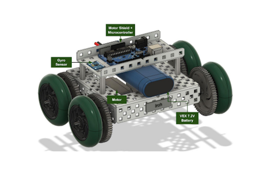
Figure 1 shows a design of a mini-VEX robot that uses a motor shield, two motors, a microcontroller, battery, and a gyro sensor.
In the EG1004 course, VEX robots are controlled using a microcontroller and a motor shield. As described in “Lab 3: Prototyping with Microcontrollers, Sensors and Materials,” a microcontroller is a programmable computer that does not use peripheral devices. When used with a motor shield, a microcontroller sends the written code or commands from Arduino to the motor shield, which is a driver module that controls the power and direction of the motors.
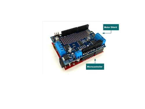
On a VEX robot, the motor shield is connected to the microcontroller and sits on top of it, as shown in Figure 2. The digital and analog pins on the motor shield are directly connected to the pins on the microcontroller.
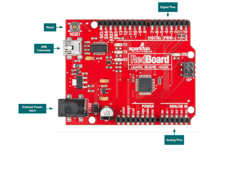
Figure 3 shows a RedBoard microcontroller that is manufactured by SparkFun Electronics. A RedBoard can be programmed with the Arduino integrated development environment (IDE). They are ideal for prototyping.
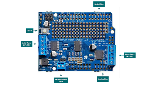
Figure 4 shows an Adafruit motor shield, which can be used to control multiple motors. A motor shield can be used with microcontrollers and Arduino IDE.
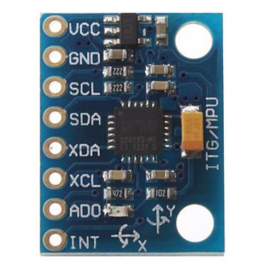
A gyroscope sensor, shown in Figure 5, is an electrical component that provides users positional and acceleration information of an object. The one shown in Figure 5 combines a 3-axis gyroscope, a 3-axis magnetometer, and a 3-axis accelerometer. When used with a VEX robot, a gyro sensor can make precise turns by repeatedly reading the robot’s position until it reaches the degree to which it is programmed to turn. This would be especially useful in the LAZ semester-long design project.
Arduino
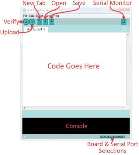
Arduino IDE is a program that can be used to edit, compile, and upload code to a supported microcontroller. Figure 6 displays the Arduino interface.
- Verify : Checks code for errors and points to those errors after it finishes
- Upload : Verifies code and then uploads it to the Arduino board if there are no errors
- Console : Shows any errors the software found in the hardware
- Serial Monitor : A tool used to send and receive messages to and from the board
Arduino Programs & VEX
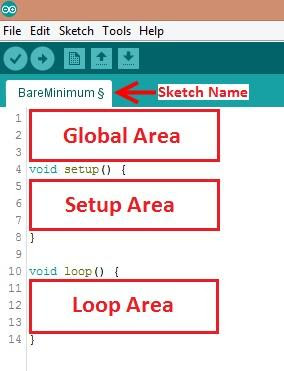
Programs written in Arduino are called sketches. A basic sketch can be broken up into three different areas: Global, Setup, and Loop. These areas are pictured in Figure 7.
- Global : Constants and imported libraries go here. VEX Library will be included in this area
- Setup : Functions will run once at the beginning of the program. Setup Area is often used to activate the pins and sensors used in the program. When using the VEX Library, the VEX robot and any sensors used will be initialized in this area
- Loop : Runs continuously after the Setup Area. Code included in the loop function will continue to run until the Arduino loses power
VEX Library Guide
The VEX Library is used in the EG1004 course to control the VEX robot and its sensors using Arduino. The library is designed to more easily access the robot’s functionality. This workshop will mainly focus on the following three sections of the library.
- Importing the library
- Vex Class
- Gyro Class
This guide also includes information on other sensors, such as ultrasonic, touch, and infrared obstacle avoidance sensors, that can be used on VEX MRR and VEX LAZ courses and help with setting up the electrical components of the VEX robot.
Materials and Equipment
- Pre-built mini-VEX robot
- Mini-VEX course
- Gyro sensor
- Arduino
Procedure
Course Breakdown
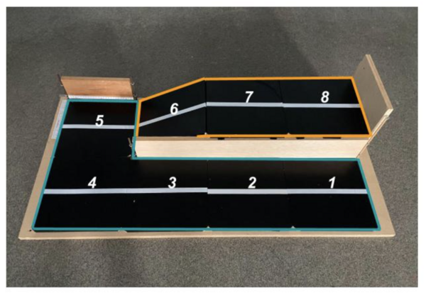
The VEX robot should navigate the mini-course shown in Figure 8 from Tile 1 to Tile 5 using the gyro sensor to complete the 90° turn. If time remains, the VEX robot should attempt to navigate up the ramp from Tile 5 to Tile 8.
1. Importing the Library
- Download the VEX Library. Unzip the file by right-clicking the file and selecting Extract All
- Open Arduino and create a new sketch.
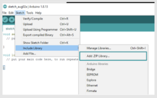
- At the top of the screen, click on Sketch, Include Library, and Add .ZIP Library (Figure 9).
- Find the unzipped folder and select the library. Upload all four files in EG VEX Libraries. Note: Arduino prevents uploading all of the libraries at once so repeat step 3.
- Once all of the libraries are imported, add #include <Vex.h> to the Global Area of the sketch, as shown in Figure 10.
2. Setting up a VEX object
To create a Vex object, the constructor must be called. Creating a Vex object allows the methods, or functions, within the Vex Class to be called on.
- In the Global Area of the sketch, create a Vex object named Robot by adding the line in Figure 11. Feel free to change the name of the VEX object.
- Initialize the Vex robot by calling on the begin() method. In the Setup Area of the sketch, add the line shown in Figure 12.
- Initialize the VEX Motors by creating motor objects and using the setMotor() method to set up the motors for use with the motor shield. In the Global Area of the code, add the lines shown in Figure 13. The value of the Motor Shield Port should match the ports the VEX motors are wired to.
- Move the VEX robot by calling on the moveTank() method. In the Loop Area of the code, add the line shown in Figure 14. The code will move the robot in a straight line. Feel free to experiment with different motor speeds and runtimes.
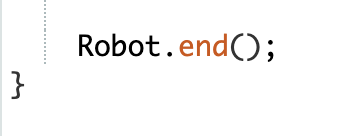
- Since Arduino will continuously loop any code in the Loop Area, call the end() method to make the program come to a stop. Before uploading the code to the microcontroller, call the end() method at the very end of the Loop Area (Figure 15).
- Compile and upload the code to the microcontroller.
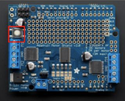
- The Vex robot will automatically run the program. To restart, hit the reset button on the motor shield (Figure 16).
- Test the robot on the course and adjust the moveTank() method as needed. Once the robot successfully reaches Tile 4, move on to Part 3.
3. Setting up a Gyro Sensor
The gyro class is used to interface with the MPU6050 accelerometer and gyroscope. It is created specifically to provide the values of the Euler angles as measured by the gyroscope.
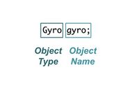
- In the Global Area of the sketch, create a Gyro object named gyro by adding the line shown in Figure 17.
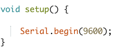
- Set up Arduino’s serial monitor to print the values the gyroscope is reading and help with debugging. In the Setup Area of the program, add the line shown in Figure 18.
- Initialize the gyro sensor in the Setup Area by using the begin() method (Figure 19).
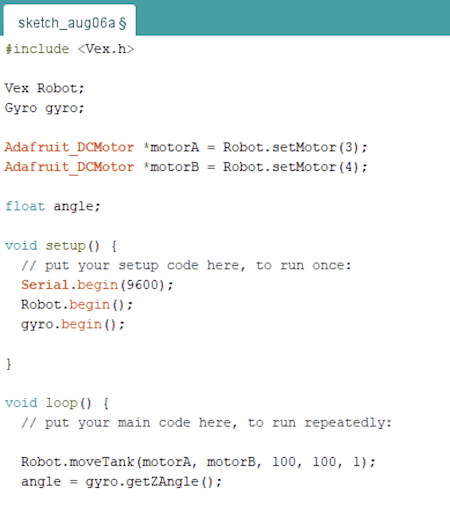
- Create a variable of type float in the Global Area to store the value read by the gyro. Call the getZAngle() method and store it in the variable. The code should look like the code shown in Figure 20.
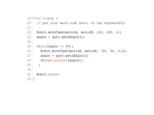
- Create a while loop that ends once the robot has turned 90° by adding the lines of code shown in Figure 21 to the Loop Area.
- Line 25
- Reads the variable angle, which stores the robot’s initial angle, and checks if it is at 90º. Since the gyro sensor was used for the first time, it should read a value around 0º. Note: If the gyro is used more than once, the getZangle() method will store the last angle it turned. Take that into consideration when programming the next turn.
- Line 26: Uses the moveTank() method to turn the robot. One way of turning a VEX robot is to set one motor to a positive power and the other to a negative power. Note: The gyro sensor is very sensitive. For best results, have the Vex robot turn in small time increments. In the code pictured, the robot turns every 0.2 s (Figure 22).
- Line 27: Calls the getZAngle() method again to update the current value of the variable angle after the robot turned in the previous line.
- Line 28: Prints the updated value of angle in the serial monitor. Printing is useful for debugging the gyro sensor and finding the angle the robot needs to make a precise turn.
- Test the robot on the course and adjust Line 25 and Line 2 as needed.
Assignment
Individual Lab Report
There is no lab report for Lab 4.
Team PowerPoint Presentation
There is no team presentation for Lab 4.
References
MPU 6050 tutorial: How to program MPU 6050 with Arduino. Arduino Project Hub. (n.d.). Web, January 14, 2022, https://create.arduino.cc/projecthub/MissionCritical/mpu-6050-tutorial-how-to- program-mpu-6050-with-arduino-aee39a
Appendix
Wiring VEX Motors
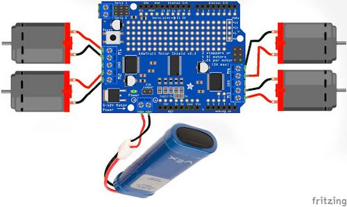
VEX motors are wired to an Adafruit motor shield. The shield is connected to the microcontroller and can receive commands from Arduino. To use the motor terminals labeled M1, M2, M3, and M4, the shield must be powered by an external power source. Figure 23 shows how to wire the motor shield with four DC motors and a 7.2V VEX battery.
Wiring a Gyro Sensor
Figure 24 shows how to wire the MPU6050 gyro sensor. Note that the int pin on the MPU6050 must be connected to digital pin 2 for the sensor to work within the VEX Library.
- VCC : 3V or 5V
- GND : Ground
- SCL : Analog Pin 5
- SDA : Analog Pin 4
- INT : Digital Pin 2
