Difference between revisions of "Virtual Circuit Simulation Guide"
From EG1004 Lab Manual
| Line 30: | Line 30: | ||
<h3>Interface</h3> | <h3>Interface</h3> | ||
* Fritzing is a free, open-source software that includes a variety of tools. A link to download can be found [ | * Fritzing is a free, open-source software that includes a variety of tools. A link to download can be found [[Media: Fritzing.zip |here]]. It is a very similar interface to TinkerCAD, with the exception that it cannot perform simulations. However, Fritzing allows for a much greater variety of components that are not included on TinkerCAD. | ||
* Upon installation, the following tabs are shown. The breadboard is the visual interaction with components, and the code is an in-program access for Arduino | * Upon installation, the following tabs are shown. The breadboard is the visual interaction with components, and the code is an in-program access for Arduino | ||
Revision as of 18:40, 6 July 2020
Circuitry
Please refer to the overview of overview section of Lab 5 if you are unfamiliar with prototyping or electrical components. It is important to have a good understanding of how circuits, microcontrollers, and breadboards work to be able to simulate said components virtually.
This guide will focus on two options for virtual circuitry, one for simulation and one for more advanced circuit creation. It is highly recommended that you utilize these softwares, but you are welcome to use any form of simulation that you deem satisfactory.
Simulation Software
Interface
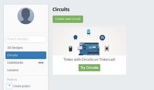
- TinkerCAD is a free in-browser software that will be used for simulation of microcontrollers and associated electrical components. A link to the website can be found here. After making an account, a circuit project can be created by clicking “create new circuit”
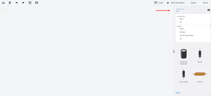
- The sidebar allows for access to common electrical components, as well as generic setups for prototyping for microcontrollers.
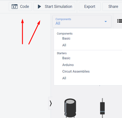
- TinkerCAD allows for the user to directly code within the software. When the circuit is ready, click “start simulation” to simulate powering the circuit.
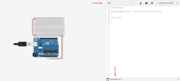
- Select “text-based” upon opening the simulation. A guide to coding with Arduino can be found here. The serial monitor window functions the same as it would in the Arduino IDE, and must be initialized in the same fashion. Note that the circuit cannot be adjusted while the code tab is opened.
Drawing Circuitry
Interface
- Fritzing is a free, open-source software that includes a variety of tools. A link to download can be found here. It is a very similar interface to TinkerCAD, with the exception that it cannot perform simulations. However, Fritzing allows for a much greater variety of components that are not included on TinkerCAD.
- Upon installation, the following tabs are shown. The breadboard is the visual interaction with components, and the code is an in-program access for Arduino
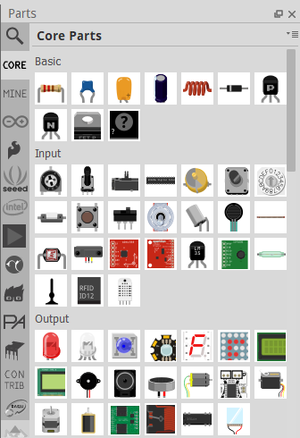
- The parts menu is the same interface as TinkerCAD, with many more options.
Basic Examples
- In this guide, two basic example projects will be shown to you on TinkerCAD, but can be easily replicated on Fritzing: a DC motor running continuously in one direction, and a DC motor that spins based on the input of the user.
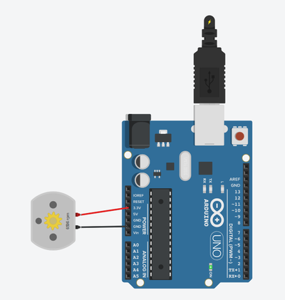
- After dragging in a DC motor and Arduino, the proper wiring is drawn and the simulation is run.
- The DC motor now displays the RPM that it would be at for this amount of voltage, specifically at 3.3 V. Note that in this situation, the microcontroller is functioning directly as a battery. Were this a 9 V battery instead of a microcontroller, the displayed RPM would be much higher if the DC motor is able to take it.
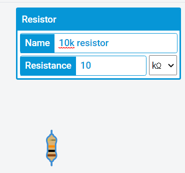
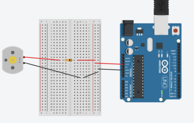
- When creating this same setup in a real scenario, it is highly unlikely that the motor will be directly connected to the power supply. Additionally, buffers such as resistors are used to prevent damage to the motor from being directly exposed to the power supply or to manipulate the RPM to a desired quantity. As such, we will drag a breadboard and resistor to the circuit. With all electrical components, TinkerCAD allows for the user to directly set the quantity in question; a resistor is dragged in and is set to 10k Ohms.
- As seen in the figure above, the RPM of the motor is decreased greatly, despite the input voltage being the same. By utilizing a breadboard, one is able to directly control how fast the motor will spin purely using resistors.
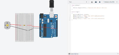
- However, this is an example of a circuit where the user has no control over the system; the motor can only run continuously in a single direction. Let’s look at an example where the motor is coded to spin back and forth on a timer.
- In the above figure, note that the power supply now is wired from pin 8. As pin 8 is a digital pin, it only has two values: HIGH or LOW. In our code, the function digitalWrite is sending signals to the specified pin. Here, HIGH will cause the pin to supply power, while LOW shuts off the power being supplied to the circuit. For the Arduinos, we will be using digital pins that will convey signals utilizing 5 Volts, hence a resistor is used to protect the motor from burning out from too much voltage. The delay function tells the microcontroller how long to follow the prior line. In this example, the motor is running for one second, then stopping for one second. As it is in a loop, it then repeats.
