Difference between revisions of "VEX Library Guide"
(→Pins:) |
(1003 --> 1004) |
||
| Line 1: | Line 1: | ||
=Vex Library= | =Vex Library= | ||
The VEX library is used in the | The VEX library is used in the EG1004 course to control the VEX robot and sensors using Arduino. The library is designed to more easily access the robot’s functionality. For more information on coding with Arduino, please reference the [[Arduino Coding Guide]] | ||
The library is intended for use with the Adafruit Motor Shield V2, and VEX EDR 2-wire motors. | The library is intended for use with the Adafruit Motor Shield V2, and VEX EDR 2-wire motors. | ||
Latest revision as of 18:32, 22 August 2022
Vex Library
The VEX library is used in the EG1004 course to control the VEX robot and sensors using Arduino. The library is designed to more easily access the robot’s functionality. For more information on coding with Arduino, please reference the Arduino Coding Guide
The library is intended for use with the Adafruit Motor Shield V2, and VEX EDR 2-wire motors.
The library allows you to interface with the following sensors:
- MPU6050 Accelerometer and Gyroscope Sensor
- HC SR04 and VEX Ultrasonic Sensor
- VEX Touch/Button and VEX Limit Switch Sensor
- IR Obstacle Avoidance Sensor
The library also allows for the following functions of the motor board:
- Control single motor speed and direction
- Control two motors speed and direction simultaneously
Download the library files here
Library Structure
This library relies on multiple 3rd party libraries, including MPU6050, I2Cdev, and Adafruit Motor Shield V2, as well as inbuilt Arduino libraries including Wire.
There is one main class that controls the robot:
- Vex: commands the motor shield, and controls the motors for all robot movement
There are 2 classes that control different sensors:
- Gyro: reads data from the MPU6050 and provides the Euler angles around 3 axises
- Ultrasonic: reads the distance from itself to the nearest object it senses
Examples
Example files can be found by clicking on File>Examples>Vex. These Arduino C codes provided show the possibilities of the robot and provide tests for different functions.
- Movement Test: tests the standard robot movements, such as forward, turns, and claw movement
- Gyro Library Test: tests the gyro sensor to display the x,y, and z Euler angles
- Gyro Turning Test: tells the robot to do a 90o left and right turn based on the gyro sensor
- IR Obstacle Test: tests the IR obstacle avoidance sensor
- Touch Test: tests the touch sensor/limit switch to display whether or not the button/switch is pressed
- Ultrasonic Test: test the ultrasonic sensor by telling the robot to move forward until it is 5cm away from an obstacle
Importing the Library
- Open your main Arduino File.
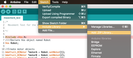
- At the top of your screen, click on ‘Sketch,’ then ‘Include Library,’ then ‘Add .ZIP Library’’
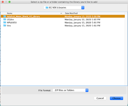
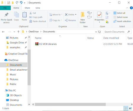
- Next, find the library you would like to include. Make sure the file is unzipped. (If using Windows, to unzip a file, right-click the file and select ‘Extract All’). You must upload all four files in ‘EG VEX Libraries.’ Note: Arduino does not let you upload all of the libraries at once so repeat steps 2 and 3.
- Make sure to have ‘#include <Vex.h> ‘ at the top of your file.
Alternative Way to Import the Library
- Download the zipped EG VEX Libraries file here
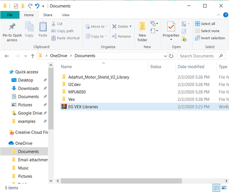
- Extract the four libraries to separate folders
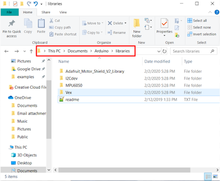
- Move the four libraries to the Arduino libraries folder
- This is usually Documents/Arduino/Libraries
- Restart the Arduino IDE to load the libraries
Vex Class
This class is used to interface with the motors connected to the Adafruit Motor Shield. The shield can support up to 4 DC motors and uses its own power source separate from the Arduino RedBoard.
Wiring
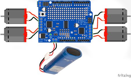
The Adafruit Motor Shield comes with pins that connect the shield directly on top of the microcontroller. The shield can then be used just like the microcontroller, as it also has the standard pins used for the Arduino. In order to use the motor terminals labeled M1, M2, M3, and M4, the shield must be powered. For the VEX library, this should be done by connecting an external power source to the terminal shown in Figure 1. Figure 1 shows how to wire the motor shield with four DC motors and an external battery.
Methods
Constructor
- In order to create a Vex object, the constructor must be called. Creating a Vex object allows you to call on the methods, which can also be referred to as functions, within the Vex Class. The constructor for a Vex object is empty meaning it has no parameters.
Syntax
- Vex vex;
Parameters
- None
Returns
- None
Example
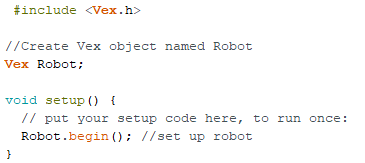
- Create a Vex object named robot:
Note: All constructors should be called outside of functions setup() and loop(). Additionally, your Vex object can have any name (i.e Robot, vex, etc).
begin()
- The begin() method initializes the VEX robot. It must be called in the setup() function to use any other Vex methods.
Note: begin() does not initialize sensors. Refer to the documentation for the wanted sensor for reference on initializing these other modules.
Syntax
- vex.begin();
Parameters
- None
Returns
- None
Example
setMotor()
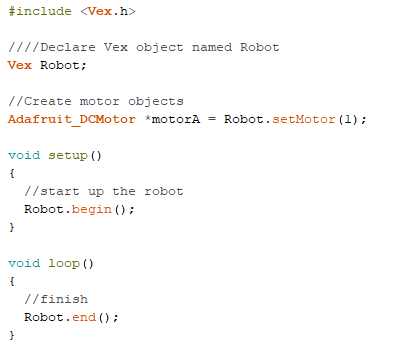
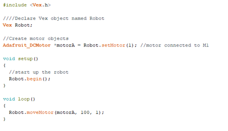
- The setMotor() method sets up the motors for use with the motor shield. This function must be called in order to create the motor objects needed for the moveMotor() and moveTank() methods. It also cannot be used alone and must be called when setting an Adafruit_DCMotor object. See the example below for correct usage of the setMotor() method
Syntax
- Adafruit_DCMotor* motor = vex.setMotor(port);
Parameters
- port: An integer between 1 and 4, representing the motor port being used on the motor shield
Returns
- An Adafruit_DCMotor* object
Example
end()
- The end() method stops all robot movement. It is meant for use at the end of the code, to stop the robot from looping the original code over and over again.
Note: this method places the code within an infinite loop, therefore any code written after this method is called will not be run.
Syntax
- vex.end();
Parameters
- None
Return
- None
Example
moveMotor()
- The moveMotor() method allows for the movement of a single motor, for a set power and time
Syntax
- vex.moveMotor(motor, power, time);
Parameters
- motor: an Adafruit_DCMotor* object, previously created using the setMotor() method.
- power: a double between -100 and 100. Positive numbers will move the motor clockwise, while negative numbers will move the motor counterclockwise. 0 will cause the motor to not move.
- time: a positive double, representing the number of seconds to run the motor.
Returns
- None
Example
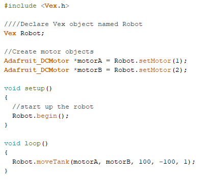
moveTank()
- The moveTank() method allows for the movement of two motors simultaneously, for two different power values, over a set period of time
Syntax
- vex.moveTank(motor1, motor2, power1, power2, time);
Parameters
- motor1: an Adafruit_DCMotor* object, previously created using the setMotor() method
- motor2: an Adafruit_DCMotor* object, previously created using the setMotor() method
- power1: a double between -100 and 100. This value controls the power of motor1. Positive numbers will move the motor clockwise, while negative numbers will move the motor counterclockwise. 0 will cause the motor to not move.
- power2: a double between -100 and 100. This value controls the power of motor2. Positive numbers will move the motor clockwise, while negative numbers will move the motor counterclockwise. 0 will cause the motor to not move.
- time: a positive double, representing the number of seconds to run the motor
Example
Gyro Class
This class is used to interface with the MPU6050 Accelerometer and Gyroscope. It is created specifically to provide the values of the Euler Angles as calculated from the gyroscope. Note: As the Gyro class is made specifically for this function, it cannot be used to access the additional functionalities of the MPU6050 device. Any other use of the MPU6050 outside of this class is at the discretion of the student.
Wiring
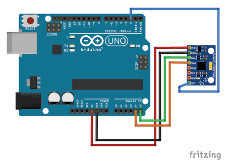
Figure 2 shows how to wire the MPU6050 sensor. Note that the Int pin on the MPU6050 must be connected to digital pin 2 on the Arduino board for the sensor to work within this library
Pins:
VCC: 3V or 5V
- GND: ground
- SCL: analog pin 5
- SDA: analog pin 4
- INT: Digital Pin 2
Methods
Constructor
- In order to create a Gyro object, the constructor must be called. Creating a Gyro object allows you to call on the methods, which can also be referred to as functions, within the Gyro Class. The constructor for a Gyro object is empty (has no parameters).
Parameters
- None
Returns
- None
Example
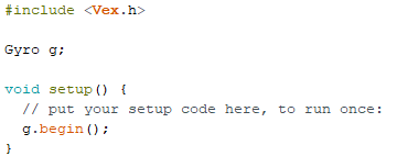
begin()
- The begin() method initializes the gyro. It must be called in the setup() function to use any other Gyro methods
Note: begin() only initializes the gyro sensor. Refer to the documentation for the wanted sensor for reference on initializing other modules
Syntax
- gyro.begin();
Parameters
- None
Returns
- None
Example
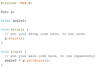
getZAngle()
- The getZAngle() method returns the calculated Euler angle about the Z-axis
Syntax
- gyro.getZAngle();
Parameters
- None
Returns
- A float (decimal) value representing the angle.
Example
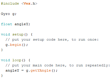
getYAngle()
- The getYAngle() method returns the calculated Euler angle about the Y-axis
Syntax
- gyro.getYAngle();
Parameters
- None
Returns
- A float value representing the angle
Example
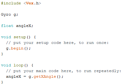
getXAngle()
- The getXAngle() method returns the calculated Euler angle about the X-axis
Syntax
- gyro.getXAngle();
Parameters
- None
Returns
- A float value representing the angle
Example
Ultrasonic Class
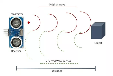
The Ultrasonic Sensor is used to determine how far away an object is. This is useful for obstacle avoidance. The HC-SR04 ultrasonic sensor uses a process similar to echolocation to operate. The sensor transmits a high-frequency signal, then it receives the signal after it gets reflected by the object. The sensor determines the time elapsed between transmission and reception. This can be used to calculate the distance from the sensor to the object using the speed of sound (343m/s).
Wiring
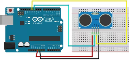
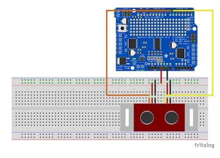
The ultrasonic sensor has four pins: Voltage (VCC), Ground (GND), Trigger (TRIG), and Echo. VCC and GND need to be connected to voltage and ground, respectively. Trigger (or transmitter) is used for the sensor to create the high-frequency signal that gets transmitted, while Echo (or receiver) is used to receive the reflected signal. Trig and Echo can be connected to any digital I/O pins. The working voltage for ultrasonic sensor is 5V, its maximum range is 4m, and its minimum range is 2cm. Male/female jumper wires can be used to connect the ultrasonic sensor to the breadboard. Figure 4A & 4B show how to correctly wire the ultrasonic sensor.
Pins
- VCC: 5V
- Trigger: digital I/O pin
- Echo: digital I/O pin
- GND: ground
Methods
Constructor
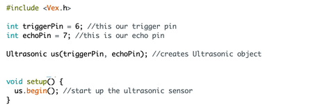
- In order to create an Ultrasonic object, the constructor must be called. The Ultrasonic constructor takes two parameters, one for the trigger pin and one for the echo pin.
Note: The Trigger and Echo Pins refer to the pin number on the Arduino/Motor Shield the trigger/echo pins are wired to.
Syntax
- Ultrasonic ultrasonic(triggerPin, echoPin);
Parameters
- triggerPin: an integer representing the digital pin used for the trigger
- echoPin: an integer representing the digital pin used for the echo
Returns
- None
Example
begin()
- The begin() method initializes the ultrasonic sensor. It must be called in the setup() function to use any other ultrasonic methods.
Syntax
- ultrasonic.begin();
Parameters
- None
Returns
- None
Example
checkUltrasonic()
- The checkUltrasonic() method returns the distance (in centimeters) between the sensor and the first object it detects.
Note: The minimum distance the sensor can detect is 2cm, while the maximum distance is 4m.
Syntax
- ultrasonic.checkUltrasonic();
Parameters
- None
Returns
- A long representing the distance (in centimeters) between the sensor and the first object it detects.
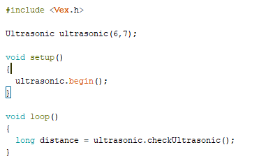
Example
Touch Class
The Touch Class is used to interface with the VEX touch sensor or VEX limit switch. The class provides boolean values representing when the switch on the sensor has been pressed.
Wiring
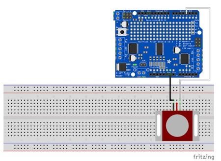
The Touch Sensor is connected to two pins on the Arduino/Adafruit MotorShield, Ground (GND) and a Digital Pin. In Figure 5, the Digital Pin is connected to Digital Pin 3. The Touch Sensor works so that whenever it is pressed, a certain line of code or function can occur.
Pins:
- GND: ground
- touchPin: Digital Pin
Methods
Constructor
- The constructor takes one parameter, for the digital pin. The constructor must be called in order to create a Touch object
Syntax
- Touch touch(pin);
Parameters
- Pin: an integer representing the digital pin used by the sensor
Returns
- None
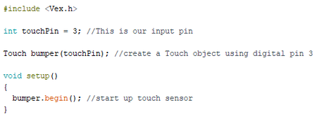
Example
begin()
- The begin() method is used to initialize the touch sensor. It must be called in the setup() function in order to use any other Touch methods
Syntax
- touch.begin();
Parameters
- None
Returns
- None
Example
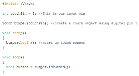
isPushed()
- The isPushed() method returns a boolean value depending on whether or not the button on the sensor has been pressed.
Syntax
- touch.isPushed();
Parameters
- None
Returns
- A boolean value. True indicates the button has been pushed, while false indicates the button has not been pushed
Example
IRObstacle Class
This class is used to interface with the IR Obstacle Avoidance Sensor. This sensor will only return whether or not there is an obstacle directly in front of the sensor.
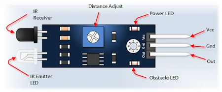
The sensor uses an infrared emitter LED. This signal is then received by an infrared receiver to determine whether or not there is an obstacle. The distance adjust terminal can be used to adjust the detection distance. Turning the screw counterclockwise will decrease the distance while turning the screw clockwise will increase the distance.
Note: As the IRObstacle class is made specifically for this function, it cannot be used to access the additional functionalities of the MPU6050 device. Any other use of the MPU6050 outside of this class is at the discretion of the student.
Wiring
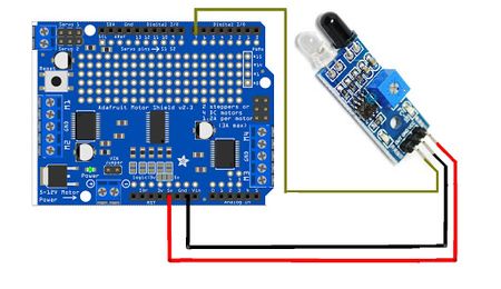
- Figure 7 shows how to wire the IR obstacle avoidance sensor
Pins:
- VCC: 3V or 5V
- GND: ground
- OUT: digital pin
Methods
Constructor
- In order to create an IRObstacle object the constructor must be called. It has one parameter for the digital pin.
Syntax
- IRObstacle ir(pin);
Parameters
- Pin: an integer representing the digital pin used for the sensor
Returns
- None
Example
begin()
- The begin() method initializes the IR obstacle avoidance sensor. It must be called in the setup() function to use any other IRObstacle methods
Note: begin() only initializes the IR obstacle avoidance sensor. Refer to the documentation for the wanted sensor for reference on initializing other modules.
Syntax
- irobstacle.begin();
Parameters
- None
Returns
- None
Example
isObstacle()
- The isObstacle() method returns a boolean value depending on whether or not the sensor detects an obstacle.
Syntax
- irobstacle.isObstacle();
Parameter
- None
Returns
- A boolean value. HIGH indicates an obstacle is detected, while LOW indicates no obstacle was detected
Example
