Difference between revisions of "Computer Aided Design Competition"
Dfrancisco (talk | contribs) m (→Overview) |
Dfrancisco (talk | contribs) |
||
| Line 69: | Line 69: | ||
* Although a specific tool such as sweep is more efficient it is not necessarily the best approach especially for beginners. Try what you know you can do. | * Although a specific tool such as sweep is more efficient it is not necessarily the best approach especially for beginners. Try what you know you can do. | ||
Revit | Revit | ||
* How can you maximize space in a very small apartment like this | * How can you maximize space in a very small apartment like this? | ||
* Consider storage and how much of it is necessary for this apartment | * Consider storage and how much of it is necessary for this apartment. | ||
* Be creative don’t just throw stuff into the space. Try and have a coherent layout | * Be creative don’t just throw stuff into the space. Try and have a coherent layout. | ||
= List of Fusion and Revit important shortcuts/hotkeys/notes = | = List of Fusion and Revit important shortcuts/hotkeys/notes = | ||
Revision as of 02:20, 8 September 2018
Pre-Lab
In order to have an understanding of this lab and be able to complete it in a timely manner it is important you view the videos that go in accordance with this lab. The required videos are on the main page of the manual.
Objectives
The experimental objectives of this lab are:
- Understand the simulation capabilities of Fusion 360, a common computer-aided design (CAD) software
- Use the basic of modeling techniques in Revit
- Understand product evaluation and minimal design concepts
Using Fusion 360 to remake a poorly design piece will introduce students to a widely used CAD modeling software and integrate common engineering techniques including: concepts of safety factor, Static stress, product evaluation and minimal design. This will led to an in house competition between all designs to determine which is the most successful and useful of a part. Designing an apartment in Revit will teach the basics of the program and give an introduction to architectural design problems.
Overview
Fusion 360
Fusion 360 is a cloud-based software (remote servers hosted via the internet that are used to process, store, and compute data) Computer Aided Design (CAD)/ Computer Aided Manufacturing (CAM)/ Computer Aided Engineering (CAE) tool that allows engineers to make precisely scaled drawings. These drawings are then turned into 3D models where they can be used to visualize concepts through photorealistic renderings, and simulate how a design performs in real world situations. Fusion 360 is a software very similar to Solidworks in the tasks you can accomplish on it as well as the layout and the tools.
The two tabs that will be used in this experiment are “Model” and “Simulation”.
In the “model” section you will find three important sections ; “Sketch”, “Create,” and “Modify”
- Sketch is the most basic tool that can be used in the software. It is used to create the shapes that will act as the bases for all 3D models. When first sketching the shapes they do not have to be true to their dimension or scale, by using the Dimension tool and Geometric Constraints tool the base shape and 3D model can be edited without starting over.
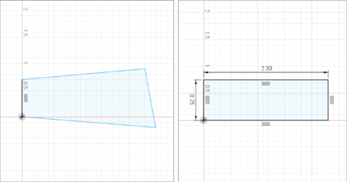
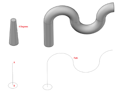
- Create is the tab where the 3D model begins to take shape. Tools such as extrude, cut and sweep, are used to give direction and depth to the 3D model The tools used in this experiment will be the Extrude and Cut tool as well as the Sweep tool. Extrude projects the initial sketch outward to create a model. Cut removes from the model a predetermined shape to a desired depth. The sweep tool creates a 3D model of a predetermined surface (sketch) along a specific path. Although this tool is more efficient than just creating multiple shapes and cutting it can be a bit challenging and so creating the shapes you want and then using a cut for this lab should be sufficient as the shapes used for supports are not more than 4 sided shapes.
- Modify contains fillet which creates a curve from an edge or corner where you can chose the radius of the curve, this can allow for a load better distributed along a surface and increase structural support.
Simulation is a very important tool that can run many different simulations in order to test how a part will do in real world situations. “Static stress” analyzes the deformation, stress, and safety factor in a model from structural loads and constraints. These assumptions are based off a linear response to stress when the load being applied is known and is constant. Using the results you can determine whether a design will deform excessively or fail (break) from the loads applied. In order to run the tests a conditions need to be set on the model.
- Constraints consist of fixed, pinned, and frictionless support reactions that prevent motion in specific directions. Fixed constraints prevent all motion and displacement of a part, this would mimic a screw holding a part in place. Pinned support prevents the movement in radial, axial, and/or tangential directions but allows a part to rotate. Frictionless constraints prevent movement normal to the surface, this mimics a wall or floor prevent motion perpendicular to the surface.
- Mesh is a boundary along the model made up of polygons where that determine the precision of the test. At every vertices the test is ran and provides the results at each point. The more polygons the more precise but the longer it takes to produce accurate results. (always generate new mesh when part is altered)
- Load is the force being applied to the model. The force is characterized by the direction, the point of application, and the magnitude being applied.
Safety Factor is a term describing how much stronger the system is than it needs to be for an intended load. It is the measure of how much load a object can sustain before permanent deformation or fracture. A common acceptable safety factor is any number above 3, anything below that is unacceptable and will likely lead to the object failing.
It is important to have a very brief understanding of physical properties of certain materials that dictate how they behave under applied loads. Modulus of elasticity is the measure of stiffness of an object. It is described as the tendency of an object to deform axially when a force is being applied in an that axial direction. Yield strength is the point at which the material begins plastic deformation begins and the shape of the object is permanently deformed. Lastly, Ultimate Tensile Strength (UTS) is the maximum stress that a material can withstand before finally failing (Bending permanently or breaking).
Autodesk Revit
Autodesk Revit is a building modeling software for architects, landscape architects, civil engineers, structural engineers, and contractors developed by Autodesk. Revit allows users to design buildings and other architectural structures in 3D while allowing for 2D drafting elements. Revit can be used to easily create various home layouts from the floor plan, electrical and plumbing, as well as design many other things.
The floor plan is the fundamental layout to any building. It is essentially the skeleton of the structure. It contains all walls, windows, and entrances to the structure and can also be furnished when being used demonstrative purposes. Different walls are used for different purposes. When designing a house, most of the interior walls are not as thick as exterior walls or walls separating public from private locations. Blueprint plans are often not furnished but to account for this architects and designers specify what the specific home in the area represents.
The electrical plan will be a part of the floor plan and demonstrates to position of all of the light fixtures and electrical appliances such as refrigerators, light switches and wires connecting lights to switches.
The plumbing plan is its own separate entity and is done on a mechanical template, as opposed to the architectural template that floor and electrical plan are on. When doing the plumbing plan it is important that the types of pipes are specified prior to the system is being created. For example, the cold water pipe and sanitation pipe need to differentiated.
Problem Specification for Revit
It is the year 2012 and you have just been contracted by New York City Mayor Bloomberg to solve a problem for many families; today, there are 1.8 million one- and two-person households in our city, but there are only about 1 million studio and one-bedroom apartments. Your task is to a create a 350-400 square foot apartment for residents/college students. This apartment should be furnished to a certain extent, it should contain a bathroom, a bed, a kitchen, a table, and a desk. Your job is to create an apartment with sufficient lighting (at least 1 window) and space so that it has all of the bare essentials. You will be tasked with creating:
- A floor plan layout of the entire apartment
- An electric and a plumbing plan for the bathroom
- (45-60 minutes for this)
Competition Specifications
- The redesigned part must not contain more than double the volume of the original part.
- For the part to be successful it must test for a safety factor above 3.
- You may not alter the applied forces, the fixed point constraints, and you cannot erase/alter the part of the model highlighted in red only add supports. It is important that the thickness of the base is not altered as you are not learning by doing this, and you are altering the proportions of the original part. However, the supports can be altered as that does not take away or add from the base of the model.
Design Considerations
Fusion 360
- You CANNOT just add a long or large block, you must try to add some intuition.
- How can thinking about bridges, cranes and other real world systems with structural support?
- What material will help increase the safety factor of the predetermined part?
- Using your knowledge of Lab 2 (Boom Construction) how can you modify these parts to support higher loads.
- Although a specific tool such as sweep is more efficient it is not necessarily the best approach especially for beginners. Try what you know you can do.
Revit
- How can you maximize space in a very small apartment like this?
- Consider storage and how much of it is necessary for this apartment.
- Be creative don’t just throw stuff into the space. Try and have a coherent layout.
List of Fusion and Revit important shortcuts/hotkeys/notes
Fusion
- L- line
- R- Rectangle
- C- circle
- D- Dimension
- F- Fillet
Revit
- WT creates windows for multiple views
- WN inserts window
- DR inserts door
- CM inserts components/furniture/appliances
Materials and Equipment
- Revit
- Fusion 360
| Material | Aluminum | Steel | Copper | Lead | Titanium |
|---|---|---|---|---|---|
| Modulus of Elasticity (MPa) | 68,900 | 210,000 | 117,500 | 14,000 | 102,810 |
| Yield Strength (MPa) | 275 | 207 | 33.3 | 8.96 | 275.6 |
| Ultimate Tensile | 310 | 345 | 210 | 18 | 344.5 |
What can and can not be edited
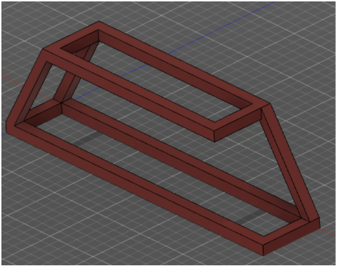
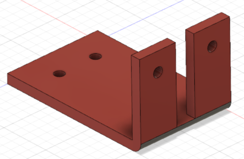
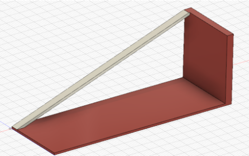
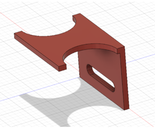
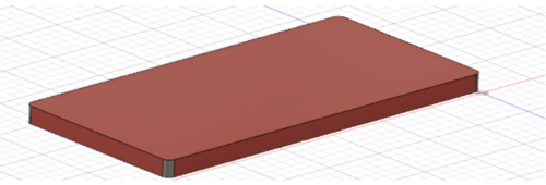
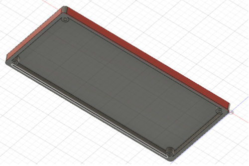
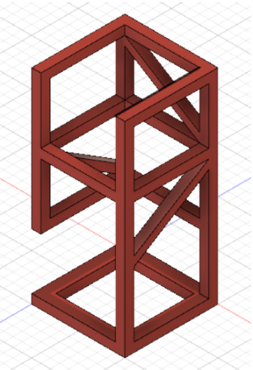
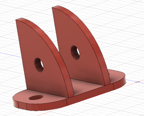
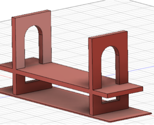
The following parts show in red what cannot be modified. The red areas cannot be cut, made longer, or thicker. However, you can add onto them such as make fillets, chamfers or other extrusions (includes lofts or sweeps).
Procedure
Fusion 360 (Part 1)
- Open the predetermined part under the “Model” tab in the drop-down menu.
- Click bodies under the left side
- Model Components→bodies→right click bodies→properties
- Record Volume in mm3
- Select the “Model” drop down menu at the top left and change it to “Simulation”
- Click “Materials” in the top toolbar and record the “study material” being used
- Determine the location the force is being exerted on
- Double click the force arrow and record the Force in Newtons
- Right click mesh then select Generate mesh
- If mesh is already generated and a popup occurs just select ok
- Right click results and select solve
- Sketch a possible solution to the broken part that would add extra support to the face where the force is being applied (At the bottom of the page are the parts with what cannot be modified). Have it approved by the TA
- Go back to the model section and use the tools showed to add the needed support to the original part
- Change the material of the part if needed as it can increase the safety factor
- Once complete go back to the simulation tab
- Right click mesh and select generate a mesh
- Run results and record safety factor
- Do not be alarmed if the model is bending a lot, the results are exaggerated to gain a better understanding of how the part moves with an applied load
- If the new part does not have a factor of safety of above 3 repeat steps 8-12
- Test the competition ratio once you have the desired safety factor
(Stop testing after 1 hour and move onto part 2)
Revit (Part 2)
- After reading the prompt, sketch your solution and indicate the square footage. Have it approved by a TA
- Open Revit and select new project, then the architectural template
- Go to Manage tab, select project units (or type UN), click under format for length and select “Feet and Fractional Inches”
- Ensure the properties tab is open by right-clicking the mouse and hitting properties
- First create the exterior walls selecting 8” thick and 10’ high walls
- You can choose to insert floor here or at the end. The floor should run along the outside of the exterior walls
- Insert the interior walls (6” thick and 10’ high) for the bathroom and any other if there are
For Steps 7-9 Look at the guide Powerpoint for needed help on walls
- Insert doors and windows in the apartment
- Go to insert→ load families→doors/windows for a wide range of doors and windows. Doors should be 3 feet wide and 7 tall (no specifications for windows)
- Only the specified furniture/appliances from the problem specification must be present in the floor plan including the entire bathroom
- Insert Tab→ Load Family→ Furniture→ Beds/Seating/Storage/Tables
- Insert Tab→Load Family→ Plumbing→ MEP→ Fixtures→ Showers/Lavatories/water closets
- Insert Tab→Load Family→ Plumbing→ MEP→ Fixtures→ Appliances→ Kitchen Unit (insert 25x84 Kitchen Unit, it includes all of the necessary kitchen appliances)
- When loading furniture or appliances go to the structure tab then select component. On the left-hand side of the properties tab, you can select whichever one of the appliances you have downloaded using load families and drag and drop into the model
- Insert a ceiling (GWB on Mtl. Stud) 9’ high
- Duplicate floor plan 1 for the electrical plan by right-clicking the first floor on properties tab then selecting “duplicate view→ duplicate” and rename the duplicate to electrical
- Go to visibility/graphics settings on properties on the electrical plan and uncheck floors, furniture, and furniture systems. This will hide unnecessary fixtures
- Insert electrical appliances into the bathroom (Slide 9 shows exactly how to do this)
- Switches: Load family → Electrical→Architectural→ Electrical Power→Terminals→Switch
- Lights: Load Family→ Lighting→ Internal→
- Connect switches and lights with detail line under annotate
- Go back to the electrical plan and scroll down on properties tab to underlay. Change “range: base level” to “level 1”, “range: Top level” to “level 2” and “underlay orientation” to “look up”.
- Save the file and close it and then open a new Revit project under the mechanical template
- Link the original Revit file under the insert section
- Place plumbing appliances (showers, sinks, toilets) in “plumbing plan 1” over the ones from the linked Revit file
- In the systems tab under plumbing select pipes
- The the properties tab scroll down to system type and change it into “Sanitary” and create a pipe starting from the corner of the apartment nearest the bathroom to the exterior of the apartment
- Click on the appliances and select the pipe under the out text and change to inherit elevation
- Take screenshots of the project and share two files, submit as zip files
Assignment
Individual Lab Report
Follow the lab report guidelines laid out in the page called Specifications for Writing Your Lab Reports in the Technical Communication section of this manual. The following points should be addressed in the appropriate section of the lab report.
- Why are CAD softwares such as Fusion 360 and its simulation capabilities important today?
- Do you think there should be a universal CAD software? What are the pros and cons of this?
- Discuss minimal design. How did having a constrained volume impact your design process?
- How did your redesign compare with other groups, did material have an impact on the safety factor and if so why?
- Why are smaller apartments such as the ones created in this lab becoming more desirable?
- How can you minimize the amount of electricity used in an apartment through architectural design?
Remember: Lab notes must be taken. Experimental details are easily forgotten unless written down. EG1004 Lab Notes Paper can be downloaded and printed from the EG1004 Website. Use the lab notes to write the Procedure section of the lab report. At the end of each lab, a TA will scan the lab notes and upload them to the Lab Documents section of the EG1004 Website. One point of extra credit is awarded if the lab notes are attached at the end of the lab report. Keeping careful notes is an essential component of all scientific practice.
Team PowerPoint Presentation
Follow the presentation guidelines laid out in the page called EG1003 Lab Presentation Format in the Introduction to Technical Presentations section of this manual. When you are preparing your presentation, consider the following points:
- Why are CAD softwares such as Fusion 360 and its simulation capabilities important today?
- Discuss minimal design. How did having a constrained volume impact your design process?
- How did your redesign compare with other groups, did material have an impact on the safety factor and if so why?
- Why are smaller apartments such as the ones created in this lab becoming more desirable?
- How can you minimize the amount of electricity used in an apartment through architectural design?
