Difference between revisions of "Investigating CO2 Production of Yeast"
| Line 55: | Line 55: | ||
== Measurements with Arduino Boards == | == Measurements with Arduino Boards == | ||
The measurements made in this lab will be made | The measurements made in this lab will be made by connecting sensors to a mictrocontroller called an Arduino. Microcontrollers are inexpensive, programmable computers that can perform simple functions. For example, microcontrollers perform specific functions in many household appliances, medical devices, cars, and other systems and devices. | ||
Arduino boards are commonly used for rapid prototyping projects. These boards come in many shapes and sizes, and some contain additional features, such as WiFi or Bluetooth connectivity. Different boards can also have different features, such as a higher processing speed and more memory. All Arduino boards have a general layout that is similar to that shown in Figure X. Key parts are listed below; in this lab, the power pins, digital pins, and analog pins will be used. | Arduino boards are commonly used for rapid prototyping projects. These boards come in many shapes and sizes, and some contain additional features, such as WiFi or Bluetooth connectivity. Different boards can also have different features, such as a higher processing speed and more memory. All Arduino boards have a general layout that is similar to that shown in Figure X. Key parts are listed below; in this lab, the power pins, digital pins, and analog pins will be used. | ||
[[Image:redboard_info.jpg|500px|thumb|center|Figure X: RedBoard Layout]] | |||
*Reset Button: Restarts the board | *Reset Button: Restarts the board | ||
| Line 76: | Line 78: | ||
*Digital Pin 13: Connected to the onboard LED, use it only as an input pin | *Digital Pin 13: Connected to the onboard LED, use it only as an input pin | ||
Arduino | == The Arduino IDE == | ||
Arduino Integrated Development Environment (IDE) is a program that can be used to edit, compile, and upload code to a supported microcontroller. Figure 7 shows a screenshot of the program's interface. | |||
* '''Verify''': Checks code for errors and points those errors | |||
* '''Upload''': Verifies code and uploads it to the Arduino board | |||
* '''Console''': Shows errors found in the hardware | |||
* '''Serial Monitor''': Sends and receives messages to and from the board | |||
[[Image:Arduino_IDE_Interface.jpeg|500px|thumb|center|Figure 7: Arduino IDE Interface]] | |||
Programs written in Arduino IDE are called sketches. A basic sketch can be broken up into three different areas: global, setup, and loop. These areas are shown in Figure 8. | |||
* '''Global''': Contains constants and imported libraries | |||
* '''Setup''': Functions that run once at the start of the program. Setup functions often are used to activate pins and sensors in the program | |||
* '''Loop''': Function runs continuously after Setup function. Code in the Loop Area will continue to run until the Arduino loses power. Function often used in most of the program to read sensors and switch pins HIGH to LOW | |||
[[Image:Sketchareas.jpg|thumb|center|Figure 8: Areas in Arduino IDE Sketch]] | |||
This lab will use a breadboard to connect sensors to the Arduino. Breadboards (Figure X) are small boards that are commonly used for circuit prototyping. They allow the circuit’s components to be connected without making permanent connections. The red and blue stripes on the sides of the board (sections A and D) are called power rails and are connected down the board, usually used for powering and grounding. The non-colored rows between the power and ground strips (sections B and C) are connected across and are usually used for making the connections between components. Sections B and C are not connected to each other across the bridge in the middle of the board. | |||
[[Image:breadboard.jpg|500px|thumb|center|Figure 12: Breadboard Connections]] | |||
The boards will be powered via connection to the Arduino. When the Arduino is powered, for example by plugging it into a PC, it can be used as a 5V voltage source. | |||
Revision as of 01:11, 22 August 2024
Objective
The experimental objective of this lab is to observe the effects of certain environmental conditions on the activity of microorganisms in a batch process. Activity will be determined by measuring production of carbon dioxide (CO_2) by rehydrated yeast in each batch and qualitative observations of the turbidity and buoyancy of the batch mixture. Predictions will be made regarding the effects of variables within the batch mixture on the yeast’s activity, and then be evaluated for validity after the batches are observed.
Overview
The use of yeast or other biological agents, such as proteins or recombinant DNA, to form useful products is an example of biotechnology. A growing field, biotechnology has led to a number of important scientific milestones; for example, in 2020, the scientists who discovered CRISPR-Cas9, an enzyme that allows gene editing, won the Nobel Prize. Their work has allowed for innovations in fields such as healthcare and agriculture. This lab provides an elementary introduction to biotechnology by investigating the reactions of yeast, a microbial fungal species commonly used to convert substrate into valuable products, like bread and alcohol.
Cellular Respiration
Yeast is a species of single-celled fungus. Fungal cells, like plant and animal cells, are eukaryotic; they contain membrane bound organelles and genetic material (Deoxyribonucleic acid, or DNA) stored within a nucleus. Cells must perform many different functions to survive, including the synthesis of proteins, the removal of waste products, and the regulation of internal conditions or homeostasis. These functions require energy obtained from the chemical energy stored within molecules consumed by the cell as food (also called substrate).
An important function is cellular respiration, which is the conversion of the substrate molecule to usable energy, a crucial portion of the cell’s metabolism. The basic reaction for cellular respiration is the conversion of the simple carbohydrate glucose (C_6H_12O_6) into carbon dioxide and water by reacting it with oxygen, and in the process releasing its chemical energy used generate the cell’s energy storage molecule Adenosine Triphosphate (ATP) as see in equation (1).
In this lab, respiration will be monitored by measuring the amount of CO_2 produced from yeast and table sugar in warm water.
Batch Processes
In lab and industrial settings, cellular respiration often takes place in a reactor known as a batch reactor, where the yeast is placed in a sealed vessel containing a reaction medium and some substrate. Environmental conditions can impact the rate of the reaction and the total amount of product produced. In this experiment, a beaker will serve as the batch reactor, water will be the medium, and the substrate will be sugar. Six batch conditions will be investigated (Table 1). In the first batch, a control experiment will provide a baseline measurement of the yeast behavior in warm water. In the second batch, table sugar will be introduced. In the third, fourth, and fifth batches, the medium will be altered by adding vinegar, soap, or salt to the solution. Last, an alternative substrate, Splenda, will be investigated.
| Condition | Substrate | Medium |
|---|---|---|
| 1 | None | Water |
| 2 | Table Sugar | Water |
| 3 | Table Sugar | Water + Vinegar |
| 4 | Table Sugar | Water + Salt |
| 5 | Table Sugar | Water + Soap |
| 6 | Splenda | Water |
It should be noted that in batch experiments, temperature should be optimized and held constant. Metabolism is dependent on temperature, as higher temperatures can increase the speed of chemical reactions within the cell. If temperatures become too high, the essential proteins within a cell begin to denature. In this exercise, temperature of the batches will be measured but not be controlled; in the time frame of the reaction, temperature should not change significantly to impact the results observed.
Measurements with Arduino Boards
The measurements made in this lab will be made by connecting sensors to a mictrocontroller called an Arduino. Microcontrollers are inexpensive, programmable computers that can perform simple functions. For example, microcontrollers perform specific functions in many household appliances, medical devices, cars, and other systems and devices.
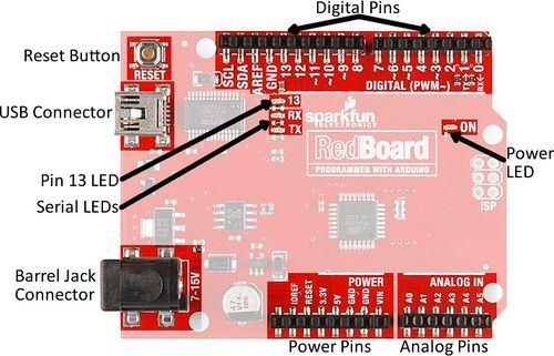
Arduino boards are commonly used for rapid prototyping projects. These boards come in many shapes and sizes, and some contain additional features, such as WiFi or Bluetooth connectivity. Different boards can also have different features, such as a higher processing speed and more memory. All Arduino boards have a general layout that is similar to that shown in Figure X. Key parts are listed below; in this lab, the power pins, digital pins, and analog pins will be used.
- Reset Button: Restarts the board
- USB Connector: Provides power and connects it to the computer
- Pin 13 LED: Usable LED without making an LED circuit
- Serial LEDs: Shows if the Arduino is transmitting or receiving data from pins 0, 1, or the USB connection
The power pins are used to supply voltage to other pins, and are also used to ground pins.
- 3.3V: Usually used to power low-voltage sensors
- 5V: Used to power circuits
- GND: Ground pin, 0V
- VIN: Voltage-in can be used to power the board using a battery or other external voltage source
The digital and analog pins are used for input and output commands to the microcontroller and electrical components. They can be used with both analog and digital devices, as the Arduino board converts analog inputs to a digital input.
- A0-A5: Identical analog pins that can read sensors or control analog devices. Analog pins can read/write values from 0 to 1023
- Digital Pins 0-1: Transmitter and receiver pins. Do not use these pins for this lab
- Digital Pins 2-12: Digital pins that switch between HIGH states and LOW states. Can only read/write values HIGH or LOW, unlike analog pins that allow a greater range of values
- Digital Pin 13: Connected to the onboard LED, use it only as an input pin
The Arduino IDE
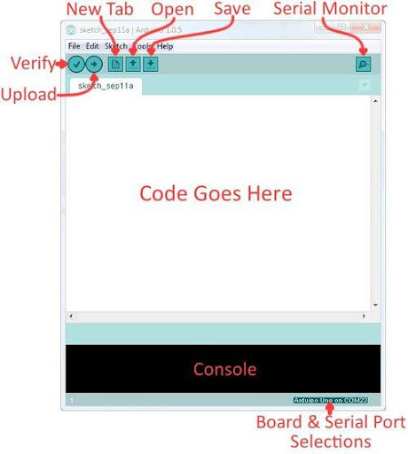
Arduino Integrated Development Environment (IDE) is a program that can be used to edit, compile, and upload code to a supported microcontroller. Figure 7 shows a screenshot of the program's interface.
- Verify: Checks code for errors and points those errors
- Upload: Verifies code and uploads it to the Arduino board
- Console: Shows errors found in the hardware
- Serial Monitor: Sends and receives messages to and from the board
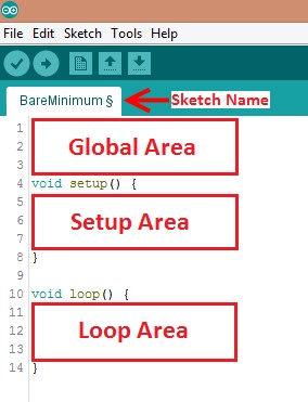
Programs written in Arduino IDE are called sketches. A basic sketch can be broken up into three different areas: global, setup, and loop. These areas are shown in Figure 8.
- Global: Contains constants and imported libraries
- Setup: Functions that run once at the start of the program. Setup functions often are used to activate pins and sensors in the program
- Loop: Function runs continuously after Setup function. Code in the Loop Area will continue to run until the Arduino loses power. Function often used in most of the program to read sensors and switch pins HIGH to LOW
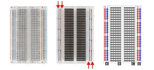
This lab will use a breadboard to connect sensors to the Arduino. Breadboards (Figure X) are small boards that are commonly used for circuit prototyping. They allow the circuit’s components to be connected without making permanent connections. The red and blue stripes on the sides of the board (sections A and D) are called power rails and are connected down the board, usually used for powering and grounding. The non-colored rows between the power and ground strips (sections B and C) are connected across and are usually used for making the connections between components. Sections B and C are not connected to each other across the bridge in the middle of the board.
The boards will be powered via connection to the Arduino. When the Arduino is powered, for example by plugging it into a PC, it can be used as a 5V voltage source.


