Difference between revisions of "Revit-How-To Guide"
| Line 23: | Line 23: | ||
Along the bottom of your window is a toolbar with various symbols. Hover over each symbol to figure out what each one does. The most important functions in this toolbar are the two symbols highlighted below (Figure 6). The first is the <b>Visual Style</b> for the model. The <b>Wireframe</b> view is the most useful style to work in because you can see through all your objects. | Along the bottom of your window is a toolbar with various symbols. Hover over each symbol to figure out what each one does. The most important functions in this toolbar are the two symbols highlighted below (Figure 6). The first is the <b>Visual Style</b> for the model. The <b>Wireframe</b> view is the most useful style to work in because you can see through all your objects. | ||
If you would like to hide certain objects while you are drawing, right click on it and click “Hide in View”. Hiding an element means only hiding the object you selected. Hiding a category means hiding every object that is in the same category as the object you selected (ex: hiding all furniture). The <b>Reveal Hidden Elements</b> function (the lightbulb symbol), when clicked, shows everything that you have hidden in pink, along with your existing structure. These two functions are helpful when you want to build on the interior of your structure, but your walls are blocking your vantage point. | If you would like to hide certain objects while you are drawing, right click on it and click “Hide in View”. Hiding an element means only hiding the object you selected. Hiding a category means hiding every object that is in the same category as the object you selected (ex: hiding all furniture). The <b>Reveal Hidden Elements</b> function (the lightbulb symbol), when clicked, shows everything that you have hidden in pink, along with your existing structure. These two functions are helpful when you want to build on the interior of your structure, but your walls are blocking your vantage point. | ||
Revision as of 03:00, 8 April 2022
Architectural
Setting up
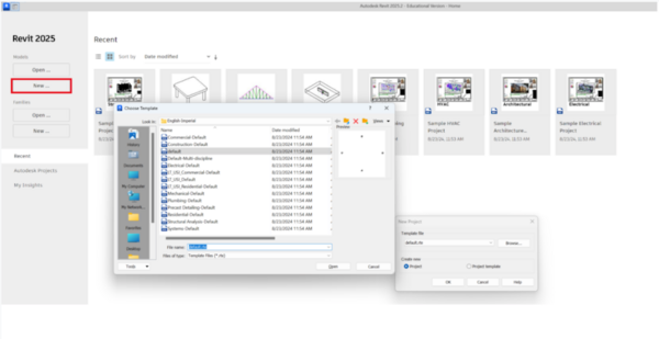
Open Revit. Select New, then select Architectural Template (Figure 1). Each template is used for a different type of design. For architectural designs, this template will be used.
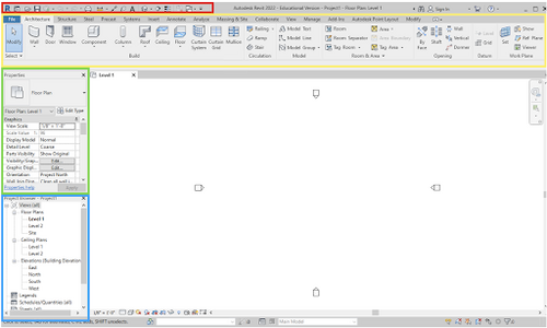
There are four major sections used to create and modify a design in Revit. The Quick Access Toolbar is highlighted in red, the Project Ribbon is highlighted in yellow, the Properties panel is highlighted in green, and the Project Browser panel is highlighted in blue (Figure 2). If any of the sections are accidentally removed from view, they can be reinserted by going to View → User Interface (rightmost icon) in the ribbon.
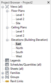
An important aspect of setting up your project is defining the levels (the story heights for the building). Navigate to one of the elevation views, in this case the East elevation, in the Project Browser by double clicking (Figure 3). Each plan view or elevation view will open in a new “tab” that you can toggle between.
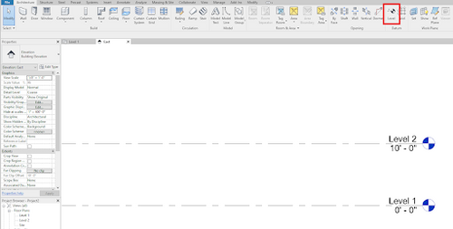
To add a new level, select Level in the Architecture tab (Figure 4). Click a point above the current top level, usually 10’, then move your cursor horizontally and click again to place the level. To delete a level, just click on it and press “Delete” on your keyboard.
To view your 3D model, go to the “View” tab in the toolbar, under the “Create” subtab, and click “3D View” (Figure 5).
Along the bottom of your window is a toolbar with various symbols. Hover over each symbol to figure out what each one does. The most important functions in this toolbar are the two symbols highlighted below (Figure 6). The first is the Visual Style for the model. The Wireframe view is the most useful style to work in because you can see through all your objects.
If you would like to hide certain objects while you are drawing, right click on it and click “Hide in View”. Hiding an element means only hiding the object you selected. Hiding a category means hiding every object that is in the same category as the object you selected (ex: hiding all furniture). The Reveal Hidden Elements function (the lightbulb symbol), when clicked, shows everything that you have hidden in pink, along with your existing structure. These two functions are helpful when you want to build on the interior of your structure, but your walls are blocking your vantage point.
Building
In the Project Browser column, go back to Level 1 under “Floor Plans”. You should always be building from the ground up, so start at Level 1. To start, select the “Wall” function under “Build” in the “Architecture” tab of the toolbar (Figure 7). Build an Architectural Wall.
When you click on the function, a new tab called “Modify” should appear on the far right of the toolbar. This happens for any new structure you select under Build. Click what type of line or shape you would like to draw and draw it on your view (Figure 8).
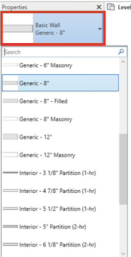
In general, your walls should be 10’ high, but this can be customized per your design. Exterior walls should be 8” thick while interior walls should be 6” thick. The thickness of the wall can be changed in the drop-down menu in the Properties panel (Figure 9).
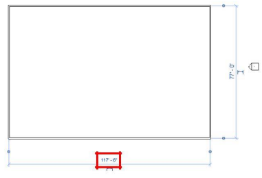
If you made a mistake in the length of your walls in your initial drawing, you can always double click on the dimension in blue and change it manually by typing in the correct value (Figure 10). Once you are done modifying the wall,or placing any component, press the “Esc” key to reset to the main screen.
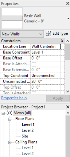
Figure 10. Modifying Wall Dimension There are other elements of the wall, or any component, that can be changed in the Properties pane (Figure 11). The Base Constraint changes where the bottom of the wall is placed in reference to the different levels. The Base Offset adjusts the height difference between the level and the base of the wall. The Top Constraint determines where the top of the wall is located. If the top constraint is unconnected, then the Unconnected Height can be used to determine a numerical value for the height of the wall.
After you have created walls for your structure (just on Level 1), you can add floors, ceilings, doors, and windows.
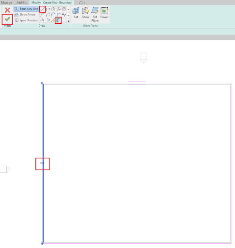
For floors and ceilings, you will need to provide a “boundary” that your floor or ceiling will follow. This boundary is the perimeter of your building that you created when you build your walls. Click “Floor”, and under the Modify tab, it will prompt you to pick a line type to draw your boundary with. “Boundary Line” should already be automatically selected. Simply click on your walls that you created, then click the green check mark. You can also create individual lines by selecting the Line tool. The arrows that appear when placing the floor allows you to toggle between the inside or the outside of your wall as the boundary (Figure 12).
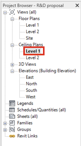
To insert a ceiling or ceiling appliance, select the Ceiling Plans in the Project Browser. Go to Level 1 in the Ceiling Plans (Figure 13).
The ceiling is created with the same method as the floor, by selecting a boundary where the ceiling will be placed. Use the Ceiling tool in the Architecture tab of the ribbon to create the ceiling. The individual walls can be selected to create the boundary by creating a Sketch Ceiling tool, or entire areas can be selected for the boundary using the Automatic Ceiling (Figure 14). Complete the ceiling by clicking the green check mark in the ribbon.
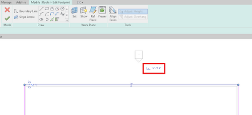
To create a roof, go to the highest level Floor Plan, and select Roof in the Architecture tab, and draw its footprints around the walls (same as a boundary). As you draw in the footprints, you can edit the slope of each portion to your liking (Figure 15). After drawing your roof footprint and clicking the green check mark, Revit will ask you if you would like to attach the highlighted walls to the roof.
Components
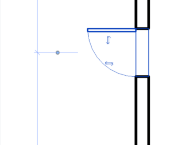
Doors and windows can be placed by selecting the respective option in the Architecture tab. They can be placed by clicking in the floor plan. Once placed, the direction of the doors and windows can be changed with the arrow couples (Figure 16).
When loading furniture or appliances, go to the Architecture tab of the ribbon and select Component → Place a Component (or type CM). Furniture and appliances can be added with the Load Family tool. Some common appliances are provided in the table below.
Table 1: File Paths for all Furniture and Appliances Tab Components File Paths Sink English → Plumbing → MEP → Fixtures → Sinks Toilet English → Plumbing → MEP → Fixtures → Water Closets Shower English → Plumbing → MEP → Fixtures → Shower Bed English → Furniture → Beds Kitchenette English → Specialty Equipment → Domestic Table English → Furniture → Tables Desk English → Furniture → Tables Door English → Door → Residential
Table 2: File Paths for Architecture Tab Components File Paths Light Switch US Imperial → Electrical → MEP → Electric Power → Terminals → Lighting Switches Ceiling Light US Imperial → Lighting → MEP → Internal
For ceiling lights, go back to the Level 1 Ceiling Plan in the Project Browser. Select the lights that are to be placed with the Component tool in the Architecture tab of the ribbon. Once the lighting fixture is selected, select Modify | Place Component → Placement → Place on Face tab of the ribbon to place the lights on the ceiling (Figure 17).
For components that are not in the default Revit library, you can visit websites such as RevitCity and BimObject. From there, you can download various components and place them as you would other components.
Stairs & Staircases
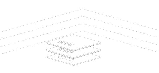
Before you add in stairs, you have to create a shaft (a hole in the ceilings and floors). In the Architecture tab, select Shaft (Figure 18).
Draw out the area of the shaft. It is recommended that the shaft you draw now is larger and you make it smaller after the staircase is placed.
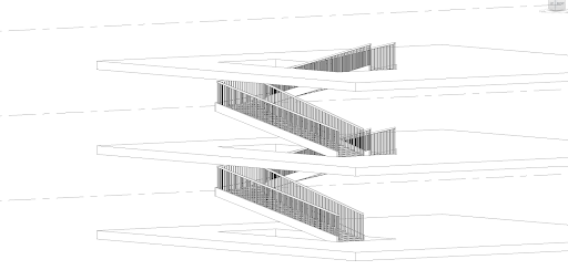
Add stairs with the “Stair” function. Place the stairs in the created shaft, you might have to adjust the “desired number of risers”(in the properties tab, under dimensions) and the “actual run width”(just under the project ribbon) so that your stairs cover the length of the entire shaft. Alternatively, you could make the shaft smaller to fit the stairs. To copy the stairs over multiple levels, select Connect Levels, a dialogue box will ask you to open a view, open any of the elevation views or 3D view and select all levels(Ctr+Click allows you to select multiple levels). Finally, click on the green check mark to finish editing.
Curtain Walls
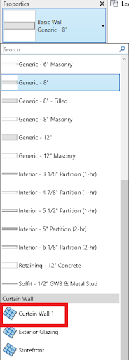
Curtain walls are made of three components: The grid, mullions, and panels. To create a curtain wall, first select a regular wall. Then, in the properties dropdown menu, select Curtain Wall (Figure 21).
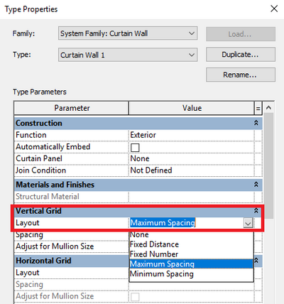
To automatically add curtain grids, select curtain wall, then select edit type in the properties browser. Under Vertical Grid → Layout, select Maximum Distance to equally divide your curtain wall, or select Fixed Distance to specify the distance between grids (Figure 22).
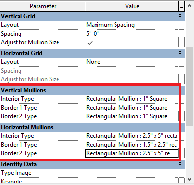
To automatically add mullions, in the same properties screen as step 4, scroll down to Vertical Mullions or Horizontal Mullions, and select the type of mullion desired (Figure 23).
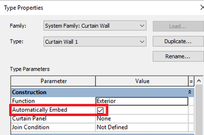
If there is a solid wall in place, a curtain wall can be embedded in it. Select the curtain wall, then in the same Edit Type menu from the previous two steps, then check the box next to Automatically Embed. Hover over the wall centerline of the wall you want to embed the curtain wall in, then place the curtain wall (Figure 24).
Plumbing
Setting up a New File
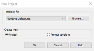
Similar to how an Architectural plan was made, select “New” under the Projects heading, then select Browse in the pop up menu, then open the template file named “Plumbing-Default.rte” (Figure 25).
Insert the architectural model by going to the “Insert” tab, then selecting Link Revit. Find the file name and select open (Figure 26).
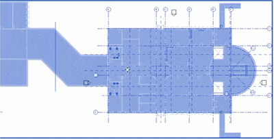
Hover over the design and left click once you see a blue box surrounding it. This should highlight every element in the design (Figure 27).
Select the pin icon under the Modify tab (Figure 28).
Inserting Fixtures
Under the “Systems” tab, select “Plumbing Fixture”. Similar to how furniture was added in the Architectural Plan, browse through the library of items and select the desired fixture. For all plumbing fixtures, use the following directory: US Imperial → Plumbing → MEP → Fixtures.
Place the new fixture near the location of the original fixture, as it won’t automatically snap over it. To align them, hit escape a few times until you are no longer under a tool, press the align tool (or press the keys A & L). Hover over the original fixture, and select on the blue line over the center of it, then select the blue line over the new fixture.
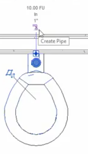
To add pipes, click on a fixture, then select the “Create Pipe” (Figure 29).
The pipe can also be routed up or down a wall, which is useful with multiple floors. Edit the height under “Middle Elevation” then click another point where you want the pipe to go. A circle will appear signifying that the pipe has moved up or down, and the rest of the pipe in the new elevation will not be visible in the current plan (Figure 30). If an error occurs when placing the pipes, try changing the elevation.
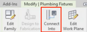
Multiple fixtures can be added to the same pipeline. Select the fixture, then click “Connect Into”, select the relevant connector type, then select the pipe, and it will automatically connect (Figure 31).
For fixtures which do not have a plumbing plan equivalent model, insert a Pipe Connecter in its place. Go to “Load Family” under “Insert”. Open the “Pipe Connector 0 Sanitary” by going through the following file directory: “Plumbing”-> “MEP”-> “Fixtures”-> “Connecters”. Select “Plumbing Fixture”, then find the Pipe Connector in the Properties sidebar. Place the connector on the wall where the fixture is attached. Click on the new connector, and like step 11, select “Create Pipe”, then route the pipe to an existing pipeline. The new pipes should be visible from the 3D view. Repeat this step for the hot and cold water connectors as needed.
Electrical
Setting up a New File
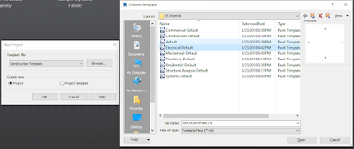
Similar to how an Architectural plan was made, select “New” under the Projects heading, then select Browse in the pop up menu, then open the template file named “Electrical-Default.rte” (Figure 32).
Insert the architectural model by going to the “Insert” tab, then selecting Link Revit. Find the file name and select open (Figure 33).
Select the pin icon under the “Modify” tab (Figure 34).
Panelboard
Next, you need to add a panelboard. In the Project Browser, select Electrical → Power → Floor Plans → 1- Power. This will show you the Level One Floor Plan of your original file. In the top menu, select Systems → Electrical Equipment→ Load Family → Electrical → MEP → Electric Power → Distribution → Lighting and Appliance Panelboard, then place the selected panelboard on a wall. Sometimes Revit will not recognize it as a Panelboard; In this case, you have to insert the Panelboard through the Component Tool.
Once placed, select escape in order to exit out of the placement tool. Next, select the Panelboard and click on “Create Panel Schedules → Default Template” in the project ribbon (Figure 35). Once selected a Branch Panel Schedule will appear. Click on the area to the right of “Branch Panel:” and rename the schedule (Usually named after the floor the panel is located on).
To add outlets, select Systems → Device → Electrical Fixture → Duplex Receptacle (GCFI if placed near a water source such as a sink, Standard otherwise), and place the outlets along the interiors of the walls.
Next, add switches. These can be found under Systems → Electrical → Device → Lighting → Lighting Switches → Circuit Breaker. Place them next to the door Next, ceiling lights will be added by going to the Project Browser and selecting Electrical → Lighting → Ceiling Plans → 1-Ceiling. Then, under the Systems tab(in the project ribbon), select Lighting Fixture, and load in the desired lights by going to Load Family → Lighting → MEP → Internal (if indoors) → then select the preferred file. Select Place on Face in the top Modify menu and attach the lights in the desired area (Figure 36).
Wires
Everything now needs to be wired. Each room needs to have two circuits. A circuit for lights and a circuit for power outlets. To start off we will generate the circuit for lights. First, select any circuit breaker(switch). Next, in the project ribbon select the “Power” button (Figure 37).
Click on the “Panel” drop-down menu and select the appropriate panelboard for the given floor (Figure 38).
Next, select “Edit Circuit” in the project ribbon (Figure 39).
Now add any component needed in the circuit with the appropriate tools in the project ribbon. Once finished, select the green check mark (Figure 40).
Hover over any of the components of the electrical circuit and click the Tab button. Next, click on the component that you hovered over. Finally select one of the two wiring options (Figure 41). If completed correctly, there should be wires in between all the circuit components and an arrow towards the circuit breaker.
Go back to the “Panel Schedule” which is located in the project browser. A new circuit should appear on the table. Rename the “Circuit Description” to an appropriate title.
Repeat this process for all rooms with lights and switches, and also to connect the outlets to the panelboard.
3D Printing
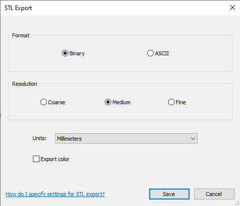
To export a floor plan from a Revit file to a STL file, open the Architectural plan. Go to File → Export → CAD Formats→ STL. The following window should appear (Figure 42). Change the units to millimeters and select Save.
