Difference between revisions of "Heat Transfer and Thermal Insulation Competition (New)"
Ldemetrious (talk | contribs) |
(1003 --> 1004) |
||
| (35 intermediate revisions by one other user not shown) | |||
| Line 140: | Line 140: | ||
<p> <b><i> Thermocouples </i></b> consist of two wires of dissimilar metals and are usually welded together or attached on a junction. When the temperature at a junction changes, it generates thermoelectric potential (emf) which is proportional to the temperature difference between the two junctions. This voltage difference can be sued to measure the temperature at that junction. </p> | <p> <b><i> Thermocouples </i></b> consist of two wires of dissimilar metals and are usually welded together or attached on a junction. When the temperature at a junction changes, it generates thermoelectric potential (emf) which is proportional to the temperature difference between the two junctions. This voltage difference can be sued to measure the temperature at that junction. </p> | ||
<p> <b><i> Thermistors <i></b> are thermally sensitive resistors that display changes in electrical resistance when subjected to a temperature change. Thermistors, like a thermocouple, utilize resistance to read temperature but do not require two different types of metal wire connected at a junction. </p> | <p> <b><i> Thermistors </i></b> are thermally sensitive resistors that display changes in electrical resistance when subjected to a temperature change. Thermistors, like a thermocouple, utilize resistance to read temperature but do not require two different types of metal wire connected at a junction. </p> | ||
<p> <b><i> Thermometers </i></b> are devices used to measure temperature or a temperature gradient utilizing a temperature sensor and some other means to convert the physical change to a digital change. Most digital thermometers utilize thermistors or lasers to calculate temperature. </p> | <p> <b><i> Thermometers </i></b> are devices used to measure temperature or a temperature gradient utilizing a temperature sensor and some other means to convert the physical change to a digital change. Most digital thermometers utilize thermistors or lasers to calculate temperature. </p> | ||
| Line 177: | Line 177: | ||
<b><font color=#ff0000>"NO RETURN" POLICY</font>: When calculating cost, you must include | |||
ALL materials you request, even if you end up not using them. Make your selections carefully | ALL materials you request, even if you end up not using them. Make your selections carefully so you don't end up with cost that hurts your performance, but has no benefit.</b> | ||
so you don't end up with cost that hurts your performance, but has no benefit.</b | |||
== Equipment Used == | == Equipment Used == | ||
| Line 186: | Line 185: | ||
* Lab PC with Arduino IDE and Python | * Lab PC with Arduino IDE and Python | ||
* Arduino board | * Arduino board | ||
* Meat Thermometer | * Meat Thermometer | ||
= Procedure = | = Procedure = | ||
| Line 204: | Line 202: | ||
more materials to be used, make sure you update your price list and your TA approves it.</li> | more materials to be used, make sure you update your price list and your TA approves it.</li> | ||
<li>Ask your TA to take a picture of your container.</li> | <li>Ask your TA to take a picture of your container.</li> | ||
</ol> | |||
== Arduino Thermistor Setup & Operation== | == Arduino Thermistor Setup & Operation== | ||
| Line 210: | Line 209: | ||
the computer. Materials used here are jumper wires, breadboard, thermistor, 10k resistor, and | the computer. Materials used here are jumper wires, breadboard, thermistor, 10k resistor, and | ||
an Arduino.</li> | an Arduino.</li> | ||
[[Image:ArduinoConnection.png|thumb|center|500px]] | [[Image:ArduinoConnection.png|thumb|center|500px|Figure 2: Thermistor connection to Arduino.]] | ||
<li>Download the [[Media: | <li>Download the [[Media:Lab 11 EG.zip|Lab 11 Folder]] and unzip it to desktop.</li> | ||
<li>In the Lab 11 Folder, find and open the '''Thermistor.ino''' file.</li> | <li>In the Lab 11 Folder, find and open the '''Thermistor.ino''' file.</li> | ||
[[Image:ThermistorLogo.png|thumb|center|500px]] | [[Image:ThermistorLogo.png|thumb|center|500px|Figure 3: Thermistor.ino file.]] | ||
<li>Click on the | <li>Click on the Tools tab from from the top of the Arduino IDE. Then click on the board and select “Arduino /Genuino Uno”.</li> | ||
[[Image: | [[Image:Step4Thermistor.png|thumb|center|500px|Figure 4: Thermistor.ino file.]] | ||
<li>Check the port from the tools tab, and select the port that the Arduino is connected to. Make sure to note the port selected.</li> | |||
[[Image:Step5Thermistor.png|thumb|center|500px|Figure 4: Thermistor.ino file.]] | |||
<li>Now UPLOAD the program to the Arduino Uno by pressing the upload button. Then close the Arduino IDE.</li> | |||
[[Image:Step6Thermistor.png|thumb|center|500px|Figure 4: Thermistor.ino file.]] | |||
<li>Now double click the DAQ.py to run the python script. You will be prompted for a COM Port number. Enter the number noted in step 5.The script will run and collect the data by it self and save a csv file. The csv file will save as DATA.csv.</li> | |||
<li>If the file with a same name exists the program will write the data in the same file.</li> | |||
</ol> | </ol> | ||
< | == Analog Meat Thermometer Usage == | ||
<ol> | |||
<li>Attach the tip of the meat thermometer to the egg and check if the temperature is reading.</li> | |||
<li>Make sure that the unit selected is Celsius.</li> | |||
</ol> | |||
< | |||
< | |||
== NI-ELVIS Circuit == | |||
<ol> | <ol> | ||
<li> | <li>Using two 100,000 Ω resistors (Brown, Black, Yellow), insert one end of each resistor into AIGND (row 18) of the NI-ELVIS board.</li> | ||
<li>Insert the other end of one of the resistors into the AI 7+ (row 15), and the end of the other resistor into AI 7- (row 16).</li> | |||
<li>Using a wire connect the AI 7+ port (row 15) to the screw terminal 1 port (row 46).</li> | |||
<li>Using a wire connect the AI 7- port (row 16) to the screw terminal 2 port (row 47).</li> | |||
<li>Insert the <span style="color: #ee8866;">orange</span> wire of the thermocouple to the screw terminal 2 jack and the <span style="color: #aaaa00;">yellow</span> wire to the screw terminal 1 jack. | |||
</ol> | |||
<span style="color: red;">Warning</span>: Make sure the metal portions of the thermocouple that enter the green screw jack do not touch! The tip of the thermocouple that is taped to the egg, however, should be twisted together. Otherwise, your results may be skewed. | |||
== Competition == | |||
<li>Download and open | <ol> | ||
<li>Secure a length of duct tape, large enough to encircle the egg, to the other end of the thermocouple, thermometer and thermistor. | |||
<li>The TA will bring the egg to you once you are ready to receive it. Attach the other end of the | Note: The thermocouple, thermistor wire and the thermometer’s tip must remain in constant contact with the egg throughout the 15-minute measurement period. Ensure that they are attached securely.</li> | ||
thermocouple to the egg using the tape you prepared. Be sure the ends of the tape overlap. Make sure | <li>Download and open Therm_VI.vi. In the lower right-hand corner of the front panel is the device name. Run the program. If no data is being recorded, stop the program and change the device name. After the correct device has been chosen, run the program for approximately 30 seconds to obtain an average room temperature. Also, use the DAQ.py file to run the Arduino program for 30 seconds to collect the room temperature. The data from the Arduino is stored in a file called DATA.csv.</li> | ||
the container is closed tightly. | <li>Using another excel file or notebook write down the average room temperature found using both the NI-ELVIS board and the Arduino.</li> | ||
<li>The TA will bring the egg to you once you are ready to receive it. Attach the other end of the thermocouple, thermistor and thermometer to the egg using the tape you prepared. Be sure the ends of the tape overlap. Make sure the container is closed tightly. | |||
Warning: Be careful! The egg is very hot.</li> | |||
<li>Start the LabVIEW VI and launch the DAQ.py program simultaneously (see Figure 2 for the VI ). Your TA will already have calibrated the VI.</li> | |||
<li>Start the LabVIEW program (see Figure 2). Your TA will already have calibrated the VI.</li> | <li>Using the stopwatch started by the TA, read and collect the Thermometer data every 15 seconds for the next 15 mins. After the time is ends stop the VI and close out of the DAQ.py program. | ||
Warning: Make sure the program is set to Run. This will allow the VI to record 30 temperature readings to an Excel spreadsheet. They will be your source data for performing necessary calculations.</li> | |||
[[Image:ThermVI.jpg|thumb|center|500px|Figure 2: Thermistor connection to Arduino.]] | |||
</ol> | </ol> | ||
== Data Analysis == | |||
<ol> | <ol> | ||
<li>Create two graphs using the X, Y Scatter template. | <li>Create two graphs using the X, Y Scatter template. | ||
You'll find the template on the <b><i>Insert</i></b> tab, under the | |||
<b><i>Charts</i></b> group, with the <b><i>Scatter</i></b> icon. Click | <b><i>Charts</i></b> group, with the <b><i>Scatter</i></b> icon. Click | ||
on the arrow below the icon and select the top left icon in the pulldown | on the arrow below the icon and select the top left icon in the pulldown | ||
| Line 264: | Line 266: | ||
<b><i>Design</i></b> tab. In the <b><i>Charts Layout</i></b> group, click the | <b><i>Design</i></b> tab. In the <b><i>Charts Layout</i></b> group, click the | ||
icon that looks like the chart you want. Right click on the things you want to | icon that looks like the chart you want. Right click on the things you want to | ||
change.</ | change.</li> | ||
<li>For each of the different devices used to collect data, name the x-axis Time. Plot it in minutes with thirty second intervals for the thermocouple (NI-ELVIS), fifteen second interval for fifteen minutes for the Thermistor(Arduino) and thermometer. You may need to divide the Arduino data by 60 to convert to minutes. T Name the y-axis Temperature. You may select the intervals based on your results. The first graph includes the first fifteen minutes of testing. The second graph is the entire time. When you are finished, your graphs should look similar to Figure 3.</li> | |||
<li>For each of | |||
minutes with thirty second intervals. Name the y-axis | |||
You may select the intervals based on your results. The first graph includes | |||
the first fifteen minutes of testing. The second graph is the entire time. When you are finished, your graphs should look similar to | |||
[[Image:Lab_hegg_7.PNG|frame|center|Figure 3: Temperature vs. Time diagram of first 15 minutes of VI run]] | [[Image:Lab_hegg_7.PNG|frame|center|Figure 3: Temperature vs. Time diagram of first 15 minutes of VI run]] | ||
<li>Calculate the <b><i>Insulating Capacity (IC) </i></b>of your design. <b><i>IC</i></b> | <li>Calculate the <b><i>Insulating Capacity (IC) </i></b>of your design. <b><i>IC</i></b> | ||
is the value of the slope of the graph of the first fifteen minutes of data. | is the value of the slope of the graph of the first fifteen minutes of data. | ||
Once again, click on the chart to get the <b><i>Design</i></b> tab on the | |||
ribbon. Under the <b><i>Chart Layouts</i></b> group, click on the chart | ribbon. Under the <b><i>Chart Layouts</i></b> group, click on the chart | ||
template that has a trend line. As before, right click on the various items to | template that has a trend line. As before, right click on the various items to | ||
| Line 285: | Line 282: | ||
an item <b><i>Display Equation on chart</i></b>. Click on the check box to the | an item <b><i>Display Equation on chart</i></b>. Click on the check box to the | ||
left of this item and click <b><i>Close</i></b>. You can then click on the | left of this item and click <b><i>Close</i></b>. You can then click on the | ||
equation that's on the chart to move it where you want.</ | equation that's on the chart to move it where you want.</li> | ||
<li>Calculate the <b><i>Minimal Design Ratio (MDR)</i></b> for your design:</li> | <li>Calculate the <b><i>Minimal Design Ratio (MDR)</i></b> for your design:</li> | ||
| Line 293: | Line 289: | ||
cost of your container, <b>T<sub>R</sub></b> is the temperature of the room given | cost of your container, <b>T<sub>R</sub></b> is the temperature of the room given | ||
to you by the TA, and <b>T<sub>F</sub></b> is the final temperature read by the | to you by the TA, and <b>T<sub>F</sub></b> is the final temperature read by the | ||
thermocouple. | thermocouple. Check the MDR using data from all the devices for a better reference. | ||
</ol> | </ol> | ||
The team with the <b><i>lowest MDR</i></b> wins. | |||
Your lab work is now complete. Please clean up your workstation. Return all | |||
unused materials to your TA. Refer to section <b><i>3 Your Assignment</i></b> | unused materials to your TA. Refer to section <b><i>3 Your Assignment</i></b> for the instructions you need to prepare your lab report. | ||
for the instructions you need to prepare your lab report. | |||
= Assignment = | |||
== Lab Report == | |||
* For | * For EG1004: This is a REQUIRED TEAM Lab Report | ||
*: <b>Note:</b> You will be writing a team lab report rather than an individual one. See the [[Team Authoring Strategies]] page in the <i>Technical Communication</i> of this online manual for guidance of how to do this. | *: <b>Note:</b> You will be writing a team lab report rather than an individual one. See the [[Team Authoring Strategies]] page in the <i>Technical Communication</i> of this online manual for guidance of how to do this. | ||
* For EGED III: This is a BONUS INDIVIDUAL Lab Report | * For EGED III: This is a BONUS INDIVIDUAL Lab Report | ||
| Line 315: | Line 310: | ||
--> | --> | ||
Follow the lab report guidelines laid out in the page called | |||
[[Specifications for Writing Your Lab Reports]] in the <i>Technical Communication</i> section of this | [[Specifications for Writing Your Lab Reports]] in the <i>Technical Communication</i> section of this | ||
manual. As you write, the following discussion points should be addressed in the appropriate | manual. As you write, the following discussion points should be addressed in the appropriate section of your lab report: | ||
section of your lab report: | |||
<ul> | <ul> | ||
| Line 331: | Line 325: | ||
<li>Discuss minimal design and its importance.</li> | <li>Discuss minimal design and its importance.</li> | ||
<li>Describe the three different types of device used to measure the temperature in this lab.</li> | |||
<li>Describe your container's design. Explain the choices you made. Make sure you include a | <li>Describe your container's design. Explain the choices you made. Make sure you include a | ||
| Line 340: | Line 336: | ||
<li>Should the <b><i>temperature vs. time </i></b>graph be smooth or should it have spikes? | <li>Should the <b><i>temperature vs. time </i></b>graph be smooth or should it have spikes? | ||
Explain how closely your curve approximates the ideal and what would affect the readings you recorded.</li> | Explain how closely your curve approximates the ideal and what would affect the readings you recorded.</li> | ||
<li>Discuss which device provided a better temperature reading. Why does one device perform better than the other? (Hint: Check the configuration, the program, the device type etc).</li> | |||
<li>Describe how your design succeeded or failed. Discuss design improvements.</li> | <li>Describe how your design succeeded or failed. Discuss design improvements.</li> | ||
| Line 347: | Line 345: | ||
</ul> | </ul> | ||
<b>Note:</b> It is not unusual to experience instrumentation errors in this lab, leading to | |||
incorrect temperatures being recorded. Be sure to read [[How to Handle Unusual Data]] in the | incorrect temperatures being recorded. Be sure to read [[How to Handle Unusual Data]] in the | ||
online manual to learn how to handle this. | online manual to learn how to handle this. | ||
{{Lab notes}} | {{Lab notes}} | ||
== Team PowerPoint Presentation == | |||
Follow the presentation guidelines laid out in the page called | |||
[[ | [[EG1004 Lab Presentation Format]] in the <i>Introduction to Technical Presentations</i> | ||
section of this manual. When you are preparing your presentation, consider the following | section of this manual. When you are preparing your presentation, consider the following | ||
points: | points: | ||
<ul> | <ul> | ||
<li>What is the importance of minimal design?</li> | <li>What is the importance of minimal design?</li> | ||
<li>Why is it important in today's world to minimize heat loss?</li> | <li>Why is it important in today's world to minimize heat loss?</li> | ||
<li>What is the importance of proper data collection method and automation?</li> | |||
<li>How would you improve your design?</li> | <li>How would you improve your design?</li> | ||
</ul> | </ul> | ||
Latest revision as of 01:55, 31 August 2022
Objectives
The experimental objective of this lab is to design and build a container that minimizes the heat lost by an egg placed inside. The heat loss will be measured by recording the temperature of the surface of the egg.
Furthermore, you will see how heat, as a form of thermal energy, can be transferred. We will also investigate the principles of minimal design. Your design will be entered in a competition against the other containers in your section. The team with the lowest Minimal Design Ratio (MDR) will be declared the winner.
Note: Be sure to read the calculation of the MDR near the end of the lab before you start your design.
Overview
Heat is a form of energy. Heat transfer is thermal energy that is transferred from one body to another as a result of a temperature difference. Temperature is the measure of the average kinetic energy of atomic motion. The faster the atoms are moving, the higher the temperature. In this lab, we will focus on the ways heat is transferred.
The specific mechanisms that convey energy from one location to another are conduction, convection, and radiation. If you put any two objects with different temperatures together, heat will be transferred from the object with the higher temperature to the one with the lower temperature until the system reaches equilibrium. Let's say you placed a hot bowl of soup on the kitchen table. What would happen? What if you placed a glass of ice water on the same table? Our job is to understand how this heat transfer occurs and how to slow the process down.
When there is a temperature difference within a solid body or between two solid bodies in contact with each other, energy (heat) will flow from the region of higher temperature to the region of lower temperature. This is known as conduction. The formula to determine the conductivity in a rod of material is:
In this equation, Q is heat transferred in time t, k is the thermal conductivity constant, A is area, T is temperature and d is the thickness of the barrier. Therefore, increasing d or decreasing A would reduce conduction.
Imagine a metal rod that is heated at one end. The atoms of the rod collide at the point where the temperature differs, transferring heat until the temperature of the rod becomes uniform.
Convection is the transfer of heat within a fluid medium (fluids consist of gasses and liquids). Convection can occur in two different ways. The first way is known as natural convection. Natural convection occurs when the main mechanism for heat transfer is due to the temperature difference either within the fluid or at its boundaries. This difference in temperature causes the molecules in the higher temperature region to expand and rise due to buoyant forces. See Figure 1 for a diagram of natural convection. The second way in which convection occurs is called forced convection. Forced convection occurs when the main mechanism for heat transfer is due to the forced flow or motion of the fluid.
Today we heat our homes through radiators using natural convection. Air flows through a heating element and then is dispersed through the room. Would it be helpful to put bigger fins on the heating element? To decide, use the formula for heat transferred through convection:
In this equation, Q is the heat transferred in time t, ∆T is the difference in temperature, h is the convection coefficient, and A is the surface area.
Suppose you wanted to disperse the heat even faster. In that case you could blow a fan past the heating elements. This is forced convection; it is one of the principles used in air conditioners to have a relatively small unit cool a large space.
According to the Encyclopedia Britannica, radiation is the process by which energy, in the form of electromagnetic radiation, is emitted by a heated surface in all directions. It travels to its point of absorption at the speed of light and does not require an intervening medium to carry it. The heating of the Earth by the Sun is an example of heat transfer by radiation. The formula for heat transferred through radiation:
In this equation, Q is the heat transferred in time t, Ts is the surface absolute temperature, is the constant of emissivity, Tsur is the surrounding absolute temperature, A is the surface area, and σ is the Stefan-Boltzmann constant.
Electromagnetic radiation is a mean of energy transfer that occurs when an atom absorbs energy. As we have seen earlier when heated atomic motion within a body increases. The energy absorbed by the atom causes some of its electrons to move around. For sake of stability, the electrons eventually come to its original state or position creating an electromagnetic wave. This EM wave can propagate as heat, light, ultraviolet, or other electromagnetic waves depending on the type of atom and the amount of energy absorbed.
Color is a property of light which is based on the frequency of the wave. When we see a specific color, our eyes literally receive an electromagnetic wave of a specific frequency. Materials that appear lighter (i.e. yellow) reflect more light (EM waves of a specific frequency) than darker ones. Following the same logic, when an object appears white, it virtually reflect all the EM waves coming to it while a "black" object absorbs it all.
Therefore, color (reflectivity) is to be considered when choosing materials for thermal insulation.
How would you feel out in the sun on hot day in a black t-shirt? How would you feel if your shirt were white? A black surface is an excellent absorber of heat, while a white surface is not. Silver is a poor heat absorber and reflects radiated energy; that is why rooftops of apartment houses are often painted silver.
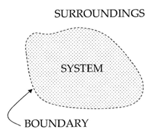
Your container is a thermodynamic system – a part of the Universe separated from the surroundings by an imaginary boundary. There are three types of systems: open systems, closed systems and isolated systems.
Open systems are systems where transfer of mass and heat is possible. For example, an open pot of boiling water is an open system – it exchanges heat with the air around it and water vapor. If collected, the water vapor can be condensed back to liquid water which has some mass.
Closed systems are systems where only heat can be transferred to the surroundings. A hermetically sealed bottle of soda is a closed system. If placed in a hot environment it absorbs energy in form of heat but the amount of liquid within does not change.
Isolated systems are systems which do not interact with the surroundings at all. No exchange is possible - neither heat nor mass. An ideal Thermos® is an isolated system. If hot chocolate is poured within, you will get the same amount back at the same temperature. No such system can be fabricated but can be approximated.
Now that we understand how heat is transferred, we must consider how to slow it down. Understanding how to minimize heat loss is the key to designing a successful insulating container.
The first consideration is the materials you choose. Using materials that are poor conductors of heat will minimize heat loss. Glass is one of these. Fiberglass insulation uses spun glass for its insulating effect.
Plastic is also a poor conductor of heat. Foam cups are made of plastic which has tiny air bubbles suspended in it. Air is among the poorest conductors of heat. It turns out that a vacuum, or the complete lack of air, is the best insulator of all. This is the principle employed in the Thermos design.
The other important consideration in creating your container is its cost. Minimal design uses the fewest resources while maintaining the safety and efficacy of your product. Engineers almost never have the luxury of designing products or systems where cost is not a factor. Given unlimited resources, you could most likely come up with a container that would maintain the egg's temperature almost indefinitely, but no one could afford to buy it from you. Balancing cost and effectiveness into your plans is a critical skill you will need later.
Another thing to consider is the method of data collection, because the way data is collected can cause many issues including providing incorrect data. To calculate changes in temperature, some devices that can be used are thermometers, thermistors, thermocouples, and RTDs.
Thermocouples consist of two wires of dissimilar metals and are usually welded together or attached on a junction. When the temperature at a junction changes, it generates thermoelectric potential (emf) which is proportional to the temperature difference between the two junctions. This voltage difference can be sued to measure the temperature at that junction.
Thermistors are thermally sensitive resistors that display changes in electrical resistance when subjected to a temperature change. Thermistors, like a thermocouple, utilize resistance to read temperature but do not require two different types of metal wire connected at a junction.
Thermometers are devices used to measure temperature or a temperature gradient utilizing a temperature sensor and some other means to convert the physical change to a digital change. Most digital thermometers utilize thermistors or lasers to calculate temperature.
In this lab, a thermocouple, thermistor, and thermometer will be used to collect data. Each of the different devices utilizes different technologies to gather the temperature data from the egg. The thermocouple collects data through the NI-ELVIS II+ board as it's built into the board itself. The thermistor operates through an Arduino. The thermometer is operated manually. This is done to check the accuracy of different types of devices and sensors as well as to determine the efficiency in the data collection method.
Competition Rules
The following rules must be observed at all times during the competition. Violation of any of these rules will result in the disqualification.
- A container (cup) must be purchased.
- All materials must be inside the container.
- The container may not be larger than the largest cup provided.
- The egg may not be returned to the water.
- The container may not be held or covered during temperature readings.
- External heat sources are prohibited.
- The egg must be inside the container within 30 seconds from when you receive it.
Design Considerations
- What materials will insulate the egg best?
- How can insulation be maximized and cost minimized?
- Which aspects of the competition formula are most advantageous?
Materials and Equipment
Materials with Price List
- Large foam cup - $0.50
- Lid - $0.25
- Paper cup - $0.40
- Styrofoam pieces - $0.05/6 pieces
- Tape - $0.10/ft
- Aluminum foil - $0.30/ft2
- Plastic wrap - $0.02/ft2
"NO RETURN" POLICY: When calculating cost, you must include
ALL materials you request, even if you end up not using them. Make your selections carefully so you don't end up with cost that hurts your performance, but has no benefit.
Equipment Used
- Lab PC with NI-ELVIS II+ Board and LabVIEW Program "Therm_VI.vi" Installed
- Lab PC with Arduino IDE and Python
- Arduino board
- Meat Thermometer
Procedure
Insulating Container Design
- Analyze your materials and consider your design options, keeping in mind the lab's specifications. Make sure you make preliminary sketches during this process.
- Now, sketch your design in pencil using the graph paper provided on the EG Website. Label your drawings clearly. Prepare a price-list for your insulating container based on the materials you have chosen. Have your TA sign the sketches and the price-list.
- Build your insulating container based on the sketch you just completed. Your TA will provide the materials needed for your design. If you decide to modify your design during the construction of your insulating container, note the changes and describe the reasons for them. If the modifications required more materials to be used, make sure you update your price list and your TA approves it.
- Ask your TA to take a picture of your container.
Arduino Thermistor Setup & Operation
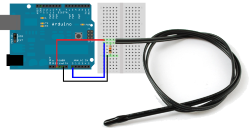
- Wire the thermistor to the Arduino in the following configuration and connect the Arduino to the computer. Materials used here are jumper wires, breadboard, thermistor, 10k resistor, and an Arduino.
- Download the Lab 11 Folder and unzip it to desktop.
- In the Lab 11 Folder, find and open the Thermistor.ino file.
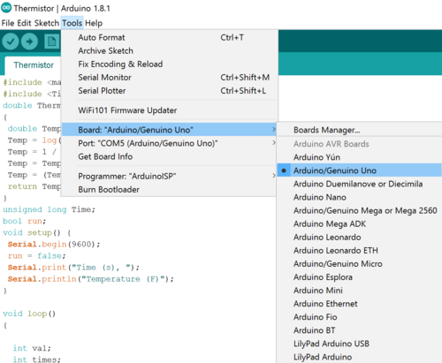
- Click on the Tools tab from from the top of the Arduino IDE. Then click on the board and select “Arduino /Genuino Uno”.
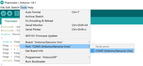
- Check the port from the tools tab, and select the port that the Arduino is connected to. Make sure to note the port selected.
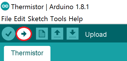
- Now UPLOAD the program to the Arduino Uno by pressing the upload button. Then close the Arduino IDE.
- Now double click the DAQ.py to run the python script. You will be prompted for a COM Port number. Enter the number noted in step 5.The script will run and collect the data by it self and save a csv file. The csv file will save as DATA.csv.
- If the file with a same name exists the program will write the data in the same file.
Analog Meat Thermometer Usage
- Attach the tip of the meat thermometer to the egg and check if the temperature is reading.
- Make sure that the unit selected is Celsius.
NI-ELVIS Circuit
- Using two 100,000 Ω resistors (Brown, Black, Yellow), insert one end of each resistor into AIGND (row 18) of the NI-ELVIS board.
- Insert the other end of one of the resistors into the AI 7+ (row 15), and the end of the other resistor into AI 7- (row 16).
- Using a wire connect the AI 7+ port (row 15) to the screw terminal 1 port (row 46).
- Using a wire connect the AI 7- port (row 16) to the screw terminal 2 port (row 47).
- Insert the orange wire of the thermocouple to the screw terminal 2 jack and the yellow wire to the screw terminal 1 jack.
Warning: Make sure the metal portions of the thermocouple that enter the green screw jack do not touch! The tip of the thermocouple that is taped to the egg, however, should be twisted together. Otherwise, your results may be skewed.
Competition
- Secure a length of duct tape, large enough to encircle the egg, to the other end of the thermocouple, thermometer and thermistor. Note: The thermocouple, thermistor wire and the thermometer’s tip must remain in constant contact with the egg throughout the 15-minute measurement period. Ensure that they are attached securely.
- Download and open Therm_VI.vi. In the lower right-hand corner of the front panel is the device name. Run the program. If no data is being recorded, stop the program and change the device name. After the correct device has been chosen, run the program for approximately 30 seconds to obtain an average room temperature. Also, use the DAQ.py file to run the Arduino program for 30 seconds to collect the room temperature. The data from the Arduino is stored in a file called DATA.csv.
- Using another excel file or notebook write down the average room temperature found using both the NI-ELVIS board and the Arduino.
- The TA will bring the egg to you once you are ready to receive it. Attach the other end of the thermocouple, thermistor and thermometer to the egg using the tape you prepared. Be sure the ends of the tape overlap. Make sure the container is closed tightly. Warning: Be careful! The egg is very hot.
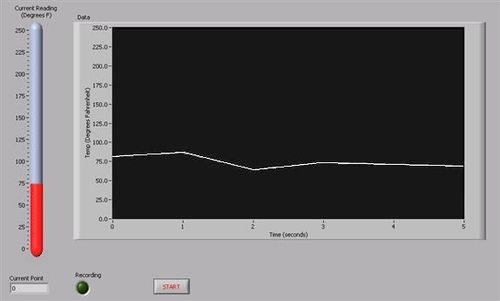
- Start the LabVIEW VI and launch the DAQ.py program simultaneously (see Figure 2 for the VI ). Your TA will already have calibrated the VI.
- Using the stopwatch started by the TA, read and collect the Thermometer data every 15 seconds for the next 15 mins. After the time is ends stop the VI and close out of the DAQ.py program. Warning: Make sure the program is set to Run. This will allow the VI to record 30 temperature readings to an Excel spreadsheet. They will be your source data for performing necessary calculations.
Data Analysis
- Create two graphs using the X, Y Scatter template. You'll find the template on the Insert tab, under the Charts group, with the Scatter icon. Click on the arrow below the icon and select the top left icon in the pulldown gallery. You can get the axes you want by clicking on the axis. You can get labels and titles by clicking on the chart, which will change the ribbon to the Design tab. In the Charts Layout group, click the icon that looks like the chart you want. Right click on the things you want to change.
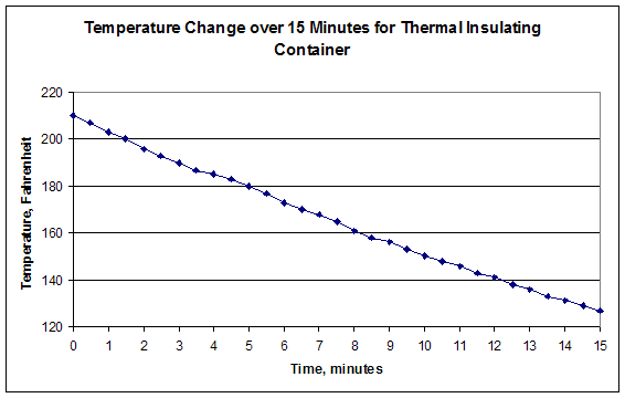
- For each of the different devices used to collect data, name the x-axis Time. Plot it in minutes with thirty second intervals for the thermocouple (NI-ELVIS), fifteen second interval for fifteen minutes for the Thermistor(Arduino) and thermometer. You may need to divide the Arduino data by 60 to convert to minutes. T Name the y-axis Temperature. You may select the intervals based on your results. The first graph includes the first fifteen minutes of testing. The second graph is the entire time. When you are finished, your graphs should look similar to Figure 3.
- Calculate the Insulating Capacity (IC) of your design. IC is the value of the slope of the graph of the first fifteen minutes of data. Once again, click on the chart to get the Design tab on the ribbon. Under the Chart Layouts group, click on the chart template that has a trend line. As before, right click on the various items to make them what you want, including deleting things. Finally, right click on the trend line. This will bring up the Format Trendline window. On the left side, the Trendline Options item should be highlighted. If it isn't, click on it to highlight it. On the right side near the bottom is an item Display Equation on chart. Click on the check box to the left of this item and click Close. You can then click on the equation that's on the chart to move it where you want.
- Calculate the Minimal Design Ratio (MDR) for your design:
IC is the insulating capacity you calculated earlier, cost is the cost of your container, TR is the temperature of the room given to you by the TA, and TF is the final temperature read by the thermocouple. Check the MDR using data from all the devices for a better reference.
The team with the lowest MDR wins.
Your lab work is now complete. Please clean up your workstation. Return all unused materials to your TA. Refer to section 3 Your Assignment for the instructions you need to prepare your lab report.
Assignment
Lab Report
- For EG1004: This is a REQUIRED TEAM Lab Report
- Note: You will be writing a team lab report rather than an individual one. See the Team Authoring Strategies page in the Technical Communication of this online manual for guidance of how to do this.
- For EGED III: This is a BONUS INDIVIDUAL Lab Report
Follow the lab report guidelines laid out in the page called
Specifications for Writing Your Lab Reports in the Technical Communication section of this
manual. As you write, the following discussion points should be addressed in the appropriate section of your lab report:
- Describe the rules of the competition in your introduction. What consequences did the rules have for your design decisions? Use the appropriate equations in your answer. You may do this in a numbered list, but please use full sentences.
- Explain equilibrium, heat, heat transfer and all the mechanisms that perform heat transfer. Discuss which of these mechanisms applied to your design.
- Define what thermal insulation is and the different types of Thermodynamic systems
- Discuss minimal design and its importance.
- Describe the three different types of device used to measure the temperature in this lab.
- Describe your container's design. Explain the choices you made. Make sure you include a discussion of the materials you chose and why. Talk about your team's strategy for winning the competition.
- What changes would have increased/decreased your MDR or IC?
- Should the temperature vs. time graph be smooth or should it have spikes? Explain how closely your curve approximates the ideal and what would affect the readings you recorded.
- Discuss which device provided a better temperature reading. Why does one device perform better than the other? (Hint: Check the configuration, the program, the device type etc).
- Describe how your design succeeded or failed. Discuss design improvements.
- Include spreadsheet with every team's results. Describe the results and talk about other designs in the class.
Note: It is not unusual to experience instrumentation errors in this lab, leading to incorrect temperatures being recorded. Be sure to read How to Handle Unusual Data in the online manual to learn how to handle this.
Remember: Lab notes must be taken. Experimental details are easily forgotten unless written down. EG1004 Lab Notes Paper can be downloaded and printed from the EG1004 Website. Use the lab notes to write the Procedure section of the lab report. At the end of each lab, a TA will scan the lab notes and upload them to the Lab Documents section of the EG1004 Website. One point of extra credit is awarded if the lab notes are attached at the end of the lab report. Keeping careful notes is an essential component of all scientific practice.
Team PowerPoint Presentation
Follow the presentation guidelines laid out in the page called EG1004 Lab Presentation Format in the Introduction to Technical Presentations section of this manual. When you are preparing your presentation, consider the following points:
- What is the importance of minimal design?
- Why is it important in today's world to minimize heat loss?
- What is the importance of proper data collection method and automation?
- How would you improve your design?



 is the constant of emissivity, Tsur is
the surrounding absolute temperature, A is the surface area, and
σ is the Stefan-Boltzmann constant.