Difference between revisions of "Sensors Guide"
| (5 intermediate revisions by the same user not shown) | |||
| Line 115: | Line 115: | ||
=== Pins === | === Pins === | ||
* GND (black wire): Ground | * GND (black wire): Ground | ||
* VCC (red wire): 5. | * VCC (red wire): 3.30 V or 5.00 V | ||
* Signal (purple/pink wire): A0, or any other analog pin | * Signal (purple/pink wire): A0, or any other analog pin | ||
| Line 128: | Line 128: | ||
==== Including the Library ==== | ==== Including the Library ==== | ||
The PulseSensor Playground library provides all the functions/methods needed to interface with the sensor. In order to use these functions, the library itself must be included at the very beginning of the Arduino file. This can be done using the | The PulseSensor Playground library provides all the functions/methods needed to interface with the sensor. In order to use these functions, the library itself must be included at the very beginning of the Arduino file. This can be done using the code pictured below in Figure 3. | ||
[[Image:bmdsg20.png|600px|thumb|center]] | |||
[[Image:bmdsg20.png|600px|thumb|center|Figure 3: Code to import sensor library]] | |||
==== Using the Library ==== | ==== Using the Library ==== | ||
In order to use the library, a PulseSensor Playground object must be created. The following code creates an object with the name pulseSensor. | In order to use the library, a PulseSensor Playground object must be created (Figure 4). The following code creates an object with the name pulseSensor. | ||
[[Image:bmdsg21.png|600px|thumb|center]] | [[Image:bmdsg21.png|600px|thumb|center|Figure 4: Declaring the Sensor Object]] | ||
Next, the sensor object must be configured and initialized. This should be done in the setup() function. In the following code, PulseWire corresponds to the analog pin the sensor is connected to and Threshold corresponds to an integer value used for detecting the heartbeat ( | Next, the sensor object must be configured and initialized. This should be done in the setup() function. In the following code, PulseWire corresponds to the analog pin the sensor is connected to and Threshold corresponds to an integer value used for detecting the heartbeat (Figure 5). A good default threshold value is 550. | ||
[[Image:bmdsg22.png|600px|thumb|center]] | [[Image:bmdsg22.png|600px|thumb|center | Figure 5:Configuring and initializing sensor]] | ||
Now that the sensor object has been started, data can now be obtained. The method <i>getBeatsPerMinute()</i> will return the BPM value read by the sensor. | Now that the sensor object has been started, data can now be obtained. The method <i>getBeatsPerMinute()</i> will return the BPM value read by the sensor. | ||
[[Image:bmdsg23.png|600px|thumb|center]] | [[Image:bmdsg23.png|600px|thumb|center|Figure 6: Data from sensor is stored into variable]] | ||
Another useful method is <i>sawStartOfBeat()</i>. This will return a | Another useful method is <i>sawStartOfBeat()</i>. This will return a Boolean value depending on whether the sensor detected a new heartbeat. In the following example, <i>sawStartOfBeat()</i> is used to print out a message followed by the current BPM every time the sensor registers a heartbeat (Figure 7). | ||
[[Image:bmdsg24.png|600px|thumb|center]] | [[Image:bmdsg24.png|600px|thumb|center|Figure 7: Heartbeat Detection Code]] | ||
| Line 149: | Line 150: | ||
== Real Time Clock (RTC) Module == | == Real Time Clock (RTC) Module == | ||
The EG-UY1004 provides a DS3231 Real Time Clock Module. As an Arduino does not keep time, RTC modules use separate batteries to keep consistent time-keeping functions | |||
[[Image:bmdsg25.png|600px|thumb|center]] | [[Image:bmdsg25.png|600px|thumb|center|Figure 1: A picture of the RTC module.]] | ||
=== Wiring === | === Wiring === | ||
Note: In order to keep time without being consistently connected to power, you must install a coin battery into the module. They do not come included with the RTC module, but EG1004 does provide CR2032 coin batteries. | Note: In order to keep time without being consistently connected to power, you must install a coin battery into the module. They do not come included with the RTC module, but EG1004 does provide CR2032 coin batteries. The following diagram in Figure 2 shows how to connect to the Arduino. | ||
[[Image:bmdsg26.png|600px|thumb|center]] | [[Image:bmdsg26.png|600px|thumb|center|Figure 2" Circuit diagram for RTC and Arduino]] | ||
=== Pins === | === Pins === | ||
| Line 167: | Line 168: | ||
==== Installing the Library ==== | ==== Installing the Library ==== | ||
The library EG1004 recommends the Adafruit’s RTClib library to interface with an RTC module. The library must be installed to the Arduino IDE in order to use the module. To download the library: | The library EG1004 recommends the Adafruit’s RTClib library to interface with an RTC module. The library must be installed to the Arduino IDE in order to use the module (Figure 3). To download the library: | ||
* Open the Arduino IDE | * Open the Arduino IDE | ||
* Go to Tools >> Manage Libraries | * Go to Tools >> Manage Libraries | ||
* Search for “RTClib” | * Search for “RTClib” | ||
* Click “Install” [[Image:bmdsg27.png|600px|thumb|center]] | * Click “Install” [[Image:bmdsg27.png|600px|thumb|center|Figure 3: RTC library]] | ||
* The IDE may ask if you wish to install “all missing dependencies”. In the case this window appears, click “Install All” | * The IDE may ask if you wish to install “all missing dependencies”. In the case this window appears, click “Install All” | ||
==== Including the Library ==== | ==== Including the Library ==== | ||
The RTClib library provides all the functions/methods needed to interface with the sensor. In order to use these functions, the library itself must be included at the very beginning of the Arduino file. This can be done using the following code: | The RTClib library provides all the functions/methods needed to interface with the sensor. In order to use these functions, the library itself must be included at the very beginning of the Arduino file (Figure 4). This can be done using the following code: | ||
[[Image:bmdsg30.png|600px|thumb|center]] | [[Image:bmdsg30.png|600px|thumb|center|Figure 4: Importing the sensor library]] | ||
==== Using the Library ==== | ==== Using the Library ==== | ||
In order to use the library, a RTC_DS3231 object must be created. The following code creates an object with the name | In order to use the library, a RTC_DS3231 object must be created. The following code creates an object with the name RTC (Figure 5). | ||
[[Image:bmdsg29.png|600px|thumb|center]] | [[Image:bmdsg29.png|600px|thumb|center|Figure 5: Object declaration]] | ||
Next, the module object must be initialized and configured. This should be done in the setup() function. To initialize the module, use the begin() method as shown below (Figure 6). | |||
[[Image:bmdsg28.png|600px|thumb|center|Figure 6: Initializing Sensor]] | |||
Now that the module object has been started, it needs to be configured in order to set the date and time (Figure 7). Only configure the time if the RTC has lost power (i.e. been disconnected from a power source or from its battery). To configure the module with the current time, use the following code: | |||
[[Image: | [[Image:bmdsg31.png|600px|thumb|center|Figure 7: Sensor configuration]] | ||
To set the module to have specific date and time, state these values in the adjust method. The code below will set the RTC to January 21, 2014 at 3:00 am (Figure 8). | |||
[[Image:bmdsg32.png|600px|thumb|center|Figure 8: Setting the time]] | |||
[[Image: | |||
Now that the RTC object has been started, data can now be obtained. The method now() will return the current date and time as a DateTime object. The code in Figure 9 creates a DateTime object called currentDT. | |||
[[Image:bmdsg33.png|600px|thumb|center|DateTime object]] | |||
[[Image:bmdsg33.png|600px|thumb|center]] | |||
This DateTime object can now be used to obtain the current year, month, day, day of the week, hour, minute, and second as set by the module. This code prints out this data using the format year/month/day (dayoftheweek) hour:minute:second (eg. 2021/2/14 (0) 14:13:30) | This DateTime object can now be used to obtain the current year, month, day, day of the week, hour, minute, and second as set by the module (Figure 10). This code prints out this data using the format year/month/day (dayoftheweek) hour:minute:second (eg. 2021/2/14 (0) 14:13:30) | ||
[[Image:bmdsg34.png|600px|thumb|center]] | [[Image:bmdsg34.png|600px|thumb|center|Figure 10: Printing time with formatting]] | ||
| Line 201: | Line 204: | ||
== Force Sensor == | == Force Sensor == | ||
EG1004 provides an Adafruit Round Force-Sensitive Resistor (FSR). These specialized resistors rely on electrical shorts for which the resistance changes depending on the pressure. | EG1004 provides an Adafruit Round Force-Sensitive Resistor (FSR). These specialized resistors rely on electrical shorts for which the resistance changes depending on the pressure. These sensors can be circular, as depicted in Figure 1, or rectangular, and the EGUY1004 Open Lab has both of these. A smaller, circular design can make readings more precise, and a rectangle shape can allow for a larger area of sensing. | ||
[[Image:bmdsg35.jpeg | [[Image:bmdsg35.jpeg|600px|thumb|center| Figure 1: Small, circular FSR]] | ||
This resistance can then be correlated to force. Figure | This resistance can then be correlated to force. Figure 2 shows the resistance vs force curve. Please note the logarithmic scale, however, the relationship is generally linear above 50g. | ||
[[Image:bmdsg37.png|600px|thumb|center|Figure | [[Image:bmdsg37.png|600px|thumb|center|Figure 2:Resistance and Force relationship for senso]] | ||
=== Wiring === | === Wiring === | ||
Note: The 10kresistor is essential for using the FSR. Do not leave it out of the circuit, | Note: The 10kresistor is essential for using the FSR (Figure 3). Do not leave it out of the circuit, | ||
[[Image:bmdsg38.png|600px|thumb|center]] | [[Image:bmdsg38.png|600px|thumb|center|Figure 3:Circuit diagram of FSR, resistor, and Arduino]] | ||
=== Code === | === Code === | ||
As the FSR provides an analog signal, analogRead() will be used to get the voltage reading from the resistor. | As the FSR provides an analog signal, analogRead() will be used to get the voltage reading from the resistor (Figure 4). | ||
[[Image:bmdsg9.png|600px|thumb|center]] | [[Image:bmdsg9.png|600px|thumb|center|Figure 4: Reading input from sensor]] | ||
This voltage reading can then be correlated to various levels of pressure. Here are the threshold values for the below example code. | This voltage reading can then be correlated to various levels of pressure. Here are the threshold values for the below example code. | ||
Table 1: Threshold Values of FSR | |||
::{| class="wikitable" | ::{| class="wikitable" | ||
!'''Threshold Value'''!!'''Pressure Reading''' | !'''Threshold Value'''!!'''Pressure Reading''' | ||
| Line 235: | Line 239: | ||
|} | |} | ||
It is recommended to test the sensor in order to determine the correct threshold for your FSR. Figure 5 below outlines a block of code that will print feedback based off of how much force the sensor is experiencing. | |||
[[Image:bmdsg39.png|600px|thumb|center]] | [[Image:bmdsg39.png|600px|thumb|center|Figure 5:Example of print statements from sensor input]] | ||
The above code works for general correlations of resistance and pressure. If you would like to measure exact values of force, [https://learn.sparkfun.com/tutorials/force-sensitive-resistor-hookup-guide/all#example-arduino-sketch SparkFun] provides a good sample code for converting the FSR reading into exact values. | The above code works for general correlations of resistance and pressure. If you would like to measure exact values of force, [https://learn.sparkfun.com/tutorials/force-sensitive-resistor-hookup-guide/all#example-arduino-sketch SparkFun] provides a good sample code for converting the FSR reading into exact values. | ||
== Muscle Sensor == | == Muscle Sensor == | ||
EG1004 provides a Myoware muscle sensor which uses electromyography (EMG) to measure muscle activity. This electrical activity is then converted into a varying voltage which can be read using an Arduino. | EG1004 provides a Myoware muscle sensor which uses electromyography (EMG) to measure muscle activity. This electrical activity is then converted into a varying voltage which can be read using an Arduino (Figure 1). | ||
[[Image:bmdsg40.png|600px|thumb|center]] | [[Image:bmdsg40.png|600px|thumb|center|Figure 1: Myoware sensor]] | ||
=== Downloads === | === Downloads === | ||
| Line 248: | Line 252: | ||
=== Wiring === | === Wiring === | ||
To use the muscle sensor, connect its electrodes to the snap connectors on the sensor board. Electrodes are electrical conductors used so electricity can enter or leave a nonmetallic object or part of a circuit. They do not come included with the muscle sensor, but EG1004 provides the muscle sensor electrodes. Figure 2 depicts the circuit diagram used to to connect the sensor to the Arduino. | |||
[[Image:bmdsg41.png|600px|thumb|center]] | [[Image:bmdsg41.png|600px|thumb|center|Circuit diagram of sensor and Arduino]] | ||
=== Pins === | === Pins === | ||
| Line 258: | Line 262: | ||
=== Code === | === Code === | ||
As the Myoware Muscle Sensor is an analog sensor, analogRead() will be used to get the analog voltage reading from the sensor. | As the Myoware Muscle Sensor is an analog sensor, analogRead() will be used to get the analog voltage reading from the sensor (Figure 3). | ||
[[Image:bmdsg3.png|600px|thumb|center]] | [[Image:bmdsg3.png|600px|thumb|center|Figure 3: Variable for analog input from sensor]] | ||
To see the value read by the sensor, use a print statement in the loop area of your code. Make sure to initialize the serial monitor by including Serial.begin(9600) in the setup area of your code. | To see the value read by the sensor, use a print statement in the loop area of your code. Make sure to initialize the serial monitor by including Serial.begin(9600) in the setup area of your code (Figure 4). | ||
[[Image:bmdsg4.png|600px|thumb|center]] | [[Image:bmdsg4.png|600px|thumb|center|Figure 4: Print statement to view values from sensor.]] | ||
Sensor values will differ depending on the placement of the electrodes (more information on electrode placement can be found [https://cdn-shop.adafruit.com/product-files/2699/AT-04-001.pdf here]). | Sensor values will differ depending on the placement of the electrodes (more information on electrode placement can be found ). It’s recommended to test the sensor multiple times to determine the different muscle values for your sensor. | ||
Sensor values will differ depending on the placement of the electrodes (more information on electrode placement can be found [https://cdn-shop.adafruit.com/product-files/2699/AT-04-001.pdf here]). The sensor should be tested multiple times to determine the different muscle values for the sensor. | |||
== Ultrasonic Sensor == | == Ultrasonic Sensor == | ||
EG1004 provides an HC-SR04 Ultrasonic sensor. This sensor uses a process similar to echolocation in order to determine how far away an object is. | EG1004 provides an HC-SR04 Ultrasonic sensor (Figure 1). This sensor uses a process similar to echolocation in order to determine how far away an object is. | ||
[[Image:bmdsg42.png|600px|thumb|center|Figure 1: Ultrasonic Sensor]] | |||
The sensor transmits a high frequency signal, then it receives the signal after it gets reflected by the object. The sensor determines the time elapsed between transmission and reception. This can be used to calculate the distance from the sensor to the object using the speed of sound (343.00 m/s). | |||
[[Image:vex_Library_21.png|600px|thumb|center|Figure | |||
[[Image:vex_Library_21.png|600px|thumb|center|Figure 2: Depiction of how waves travel between sensor and object.]] | |||
* <b>Ranging Distance: 2cm to 400cm | * <b>Ranging Distance: 2cm to 400cm | ||
* Measuring Angle: | * Measuring Angle: 15.00° | ||
* Power Supply: | * Power Supply: 5.00V</b> | ||
=== Wiring === | === Wiring === | ||
[[Image:vex_Library_22.png|600px|thumb|center]] | [[Image:vex_Library_22.png|600px|thumb|center|Figure 3: Figure 3: Circuit diagram of ultrasonic sensor]] | ||
=== Pins === | === Pins === | ||
* VCC: | * VCC: 5.00V | ||
* Trig: 11 | * Trig: 11 or any digital pin | ||
* Echo: 12 | * Echo: 12 or any digital pin | ||
* GND: Ground | * GND: Ground | ||
=== Code === | === Code === | ||
The first step in using an HC-SR04 is to set up the trigger and echo pins. In the setup() function, The trigger pin should be set to OUTPUT, and the echo pin should be set to INPUT as shown below. Here trigPin corresponds to the digital pin for the Trigger, while echoPin corresponds to the digital pin for the Echo. | The first step in using an HC-SR04 is to set up the trigger and echo pins (Figure 4). In the setup() function, The trigger pin should be set to OUTPUT, and the echo pin should be set to INPUT as shown below. Here trigPin corresponds to the digital pin for the Trigger, while echoPin corresponds to the digital pin for the Echo. | ||
[[Image:bmdsg47.png|600px|thumb|center]] | [[Image:bmdsg47.png|600px|thumb|center|Figure 4: Setting up trig and echo for ultrasonic sensor]] | ||
Code can now be written in the loop() function to collect data. The ultrasonic sensor first needs to send a HIGH pulse of 10 or more microseconds using the trigger pin. One LOW pulse is used before to ensure a clean HIGH pulse, and another LOW after stops the HIGH pulse. | Code can now be written in the loop() function to collect data (Figure 5). The ultrasonic sensor first needs to send a HIGH pulse of 10 or more microseconds using the trigger pin. One LOW pulse is used before to ensure a clean HIGH pulse, and another LOW after stops the HIGH pulse. | ||
[[Image:bmdsg48.png|600px|thumb|center]] | [[Image:bmdsg48.png|600px|thumb|center|Figure 5: code block to be looped to detect objects]] | ||
After the initial pulse has been sent out, the echo pin is then used to read the signal from the sensor. The method pulseIn() will return the time (in microseconds) from when the Trigger pin sends the ping, to when it is received by the Echo pin. | After the initial pulse has been sent out, the echo pin is then used to read the signal from the sensor (Figure 6). The method pulseIn() will return the time (in microseconds) from when the Trigger pin sends the ping, to when it is received by the Echo pin. | ||
[[Image:bmdsg49.png|600px|thumb|center]] | [[Image:bmdsg49.png|600px|thumb|center|Figure 6: PulseIn function.]] | ||
After reading the duration, the last step needed is to convert this to distance. Duration can be converted to centimeters using the following formula: | After reading the duration, the last step needed is to convert this to distance. Duration can be converted to centimeters using the following formula (1): | ||
Distance (cm) = (Duration (microseconds) /2) / 29.1 | Distance (cm) = (Duration (microseconds) /2) / 29.1 (1) | ||
Below is an example of coding this formula, in order to get the distance between the sensor and a detected object. | Below is an example of coding this formula, in order to get the distance between the sensor and a detected object (Figure 7). | ||
[[Image:bmdsg50.png|600px|thumb|center]] | [[Image:bmdsg50.png|600px|thumb|center|Figure 7: Distance equation written in code]] | ||
Latest revision as of 19:34, 2 September 2024
The purpose of this guide is to provide useful information on common sensors used in the Rapid Assembly and Design (RAD) Semester-Long Design Project (SLDP). Note that sensors made by different companies may differ from the ones mentioned in this guide, but documentation for sensors may be available online. For more information on coding with Arduino, please reference the Arduino Coding Guide.
Gas Sensor
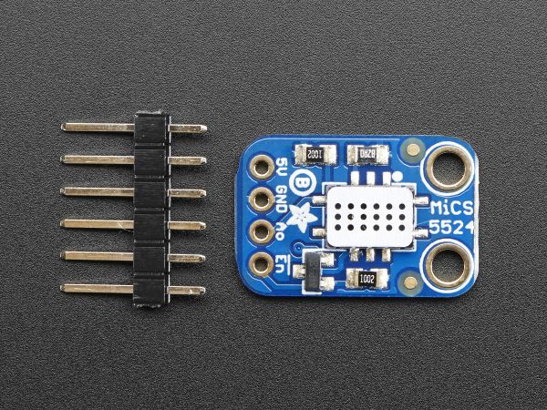
EG-UY 1004 provides an Adafruit Gas Sensor. When a gas is detected, the analog voltage will increase in proportion to the gas. This sensor is sensitive to multiple gases, but does not indicate which gas it detects (Figure 1).
Wiring
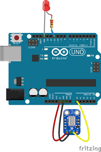
The LED used in the circuit is not required, but could be helpful for testing (Figure 2).
Pins
- VCC: 5.00V
- Signal: A0 or any analog pin
- GND: Ground
Code
As the Adafruit gas sensor is an analog sensor, analogRead() will be used to find the analog voltage reading from the sensor (Figure 3).
To see the value read by the sensor, use a print statement in the Loop area of the code. Initialize the serial monitor by including Serial.begin(9600) in the setup area of the code (Figure 4).
UV Sensor
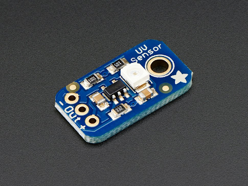
EG-UY1004 provides a GUVA-S12SD UV Light Sensor Breakout (Figure 1).
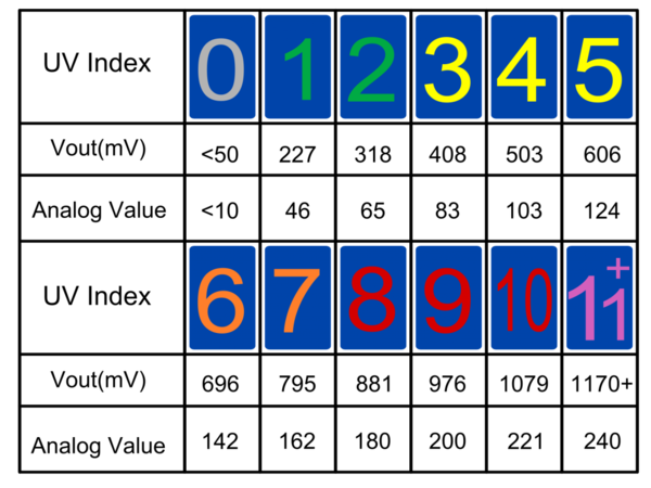
This sensor uses an UV photodiode to provide an analog voltage output that can then be converted to UV Index (Figure 2). The wavelength range of light that this sensor can measure is between 240nm to 360nm, which mostly covers the full range of UVA, UVB, and UVC radiation. The voltage it requires is between 2.7 and 5.5 V.
Wiring
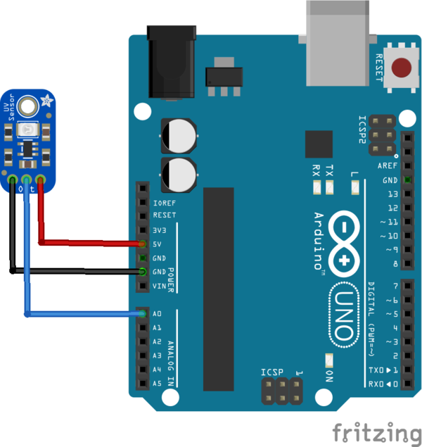
Note: the sensor can be connected to either a 3.30 V to 5.00 V power supply.
Pins
- +: 5V (or 3.3V)
- OUT: A0 (or other analog pin)
- -: Ground
Code
As the GUVA-S12SD is an analog sensor, analogRead() will be used to get the voltage reading from the sensor.
This initial reading must then be converted to voltage. The formula will differ depending on if you are using the 3.3V or 5V power supply.
- 3.3V formula → Voltage(V) = reading * (3.3/1024.0)
- 5V formula → Voltage(V) = reading * (5.0/1024.0)
Below is an example of coding this formula for a 5V power supply. Note that the numbers are in decimal form, this is required in order to get correct voltage values.
Lastly, this voltage value can be converted to an approximate UV Index using the following formula:
For example, a voltage reading of 0.5V indicates a UV index of about 5.
Temperature Sensor (TMP36)
EG1004 provides an Analog TMP36 temperature sensor. These sensors use the change in voltage to produce an analog signal that is proportional to temperature. TMP36s have a temperature range between -40oC and 150oF. Power supply: 2.7V to 5.5V
Wiring
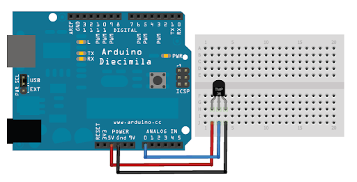
Note: the sensor can be connected to either the 5V or 3.3V power pins.
Pins
- VCC: 3.3V or 5V
- Signal: A0 (or any analog pin)
- GND: ground
Code
As the TMP36 is an analog sensor, analogRead() will be used to get the voltage reading from the sensor.
This initial reading must then be converted to Voltage. The formula will differ depending on if you are using the 3.3V or 5V power supply.
- 3.3V formula → Voltage(mV) = reading * (3300.0/1024.0)
- 5V formula → Voltage(mV) = reading * (5000.0/1024.0)
Below is an example of coding this formula for a 5V power supply. Note that the numbers are in decimal form, this is required in order to get correct temperature values.
Lastly, this voltage value needs to be converted to Celsius using the following formula:
Temperature (C) = (Voltage(mV) - 500.0) / 10.0
Below is an example of coding this formula. Once again, note the use of the decimal format for the numbers.
Pulse Sensor
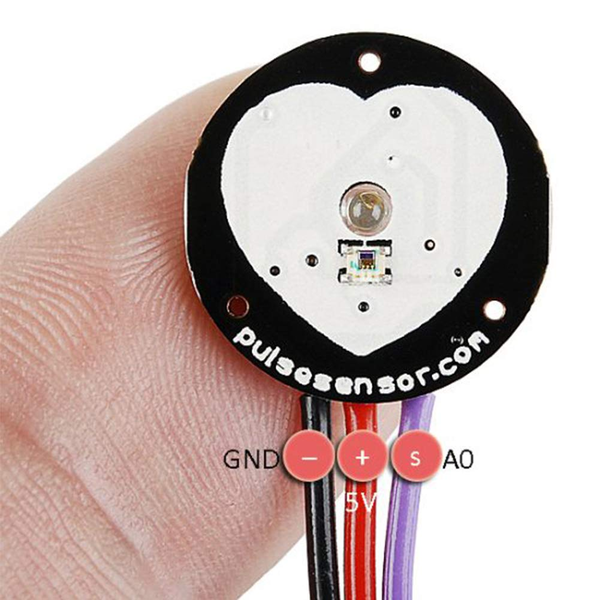
EG1004 provides an ANMBEST Pulse Sensor (Figure 1). This is an optical heart rate sensor (PPG) designed for Arduino. The sensor uses an ambient light sensor to watch for a change in reflected light that occurs when blood pumps through tissue. By setting a standard threshold value, an Arduino can watch the analog signal from the sensor.
When the signal passes the threshold, this means a heartbeat has been detected. Once the signal drops below the threshold, the Arduino will wait for the signal to pass the threshold again, indicating another heartbeat.
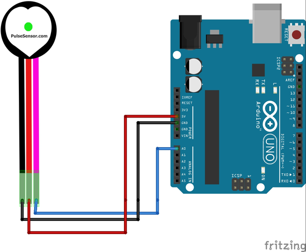
Wiring
Pins
- GND (black wire): Ground
- VCC (red wire): 3.30 V or 5.00 V
- Signal (purple/pink wire): A0, or any other analog pin
Code
Installing the Library
The PulseSensorPlayground Library must be installed to the Arduino IDE in order to use the sensor. To download the library:
- Open the Arduino IDE
- Go to Tools >> Manage Libraries
- Search for “PulseSensor Playground”
- Click “Install”
Including the Library
The PulseSensor Playground library provides all the functions/methods needed to interface with the sensor. In order to use these functions, the library itself must be included at the very beginning of the Arduino file. This can be done using the code pictured below in Figure 3.
Using the Library
In order to use the library, a PulseSensor Playground object must be created (Figure 4). The following code creates an object with the name pulseSensor.
Next, the sensor object must be configured and initialized. This should be done in the setup() function. In the following code, PulseWire corresponds to the analog pin the sensor is connected to and Threshold corresponds to an integer value used for detecting the heartbeat (Figure 5). A good default threshold value is 550.
Now that the sensor object has been started, data can now be obtained. The method getBeatsPerMinute() will return the BPM value read by the sensor.
Another useful method is sawStartOfBeat(). This will return a Boolean value depending on whether the sensor detected a new heartbeat. In the following example, sawStartOfBeat() is used to print out a message followed by the current BPM every time the sensor registers a heartbeat (Figure 7).
The PulseSensor Playground Library also comes with many example codes and tutorials. These can be found on the Pulse Sensor Website.
Real Time Clock (RTC) Module
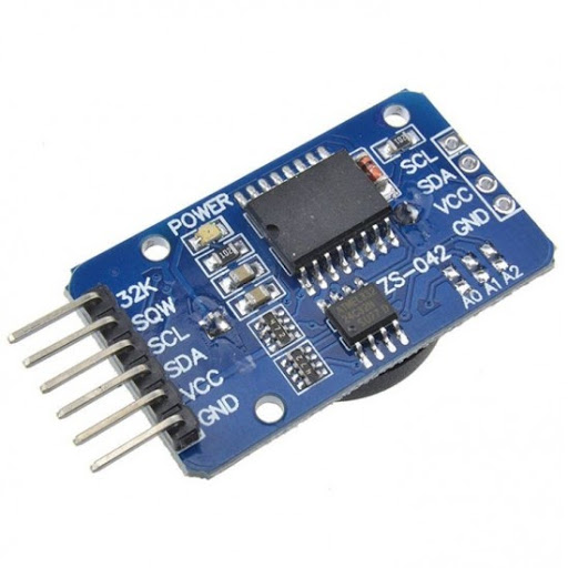
The EG-UY1004 provides a DS3231 Real Time Clock Module. As an Arduino does not keep time, RTC modules use separate batteries to keep consistent time-keeping functions
Wiring
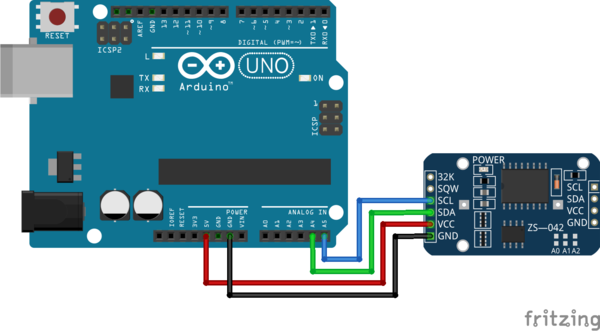
Note: In order to keep time without being consistently connected to power, you must install a coin battery into the module. They do not come included with the RTC module, but EG1004 does provide CR2032 coin batteries. The following diagram in Figure 2 shows how to connect to the Arduino.
Pins
- SCL: A5 (or SCL pin)
- SDA: A4 (or SDA pin)
- VCC: 5V
- GND: Ground
Code
Installing the Library
The library EG1004 recommends the Adafruit’s RTClib library to interface with an RTC module. The library must be installed to the Arduino IDE in order to use the module (Figure 3). To download the library:
- Open the Arduino IDE
- Go to Tools >> Manage Libraries
- Search for “RTClib”
- Click “Install”
- The IDE may ask if you wish to install “all missing dependencies”. In the case this window appears, click “Install All”
Including the Library
The RTClib library provides all the functions/methods needed to interface with the sensor. In order to use these functions, the library itself must be included at the very beginning of the Arduino file (Figure 4). This can be done using the following code:
Using the Library
In order to use the library, a RTC_DS3231 object must be created. The following code creates an object with the name RTC (Figure 5).
Next, the module object must be initialized and configured. This should be done in the setup() function. To initialize the module, use the begin() method as shown below (Figure 6).
Now that the module object has been started, it needs to be configured in order to set the date and time (Figure 7). Only configure the time if the RTC has lost power (i.e. been disconnected from a power source or from its battery). To configure the module with the current time, use the following code:
To set the module to have specific date and time, state these values in the adjust method. The code below will set the RTC to January 21, 2014 at 3:00 am (Figure 8).
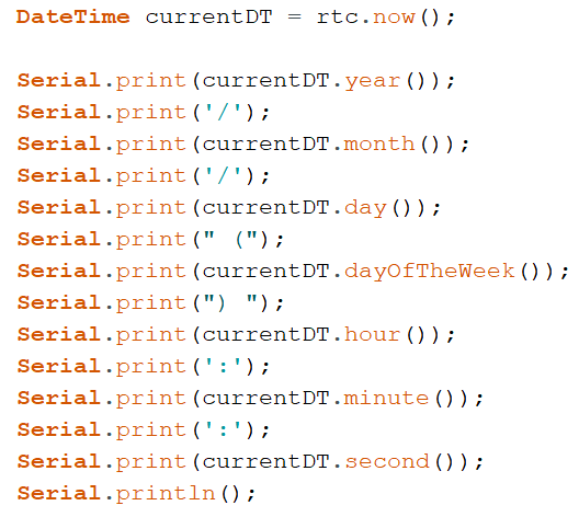
Now that the RTC object has been started, data can now be obtained. The method now() will return the current date and time as a DateTime object. The code in Figure 9 creates a DateTime object called currentDT.
This DateTime object can now be used to obtain the current year, month, day, day of the week, hour, minute, and second as set by the module (Figure 10). This code prints out this data using the format year/month/day (dayoftheweek) hour:minute:second (eg. 2021/2/14 (0) 14:13:30)
The RTClib Library also comes with many example codes. These can be found on the Arduino IDE, under File >> Examples >> RTClib.
Force Sensor
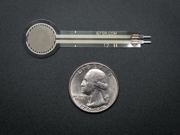
EG1004 provides an Adafruit Round Force-Sensitive Resistor (FSR). These specialized resistors rely on electrical shorts for which the resistance changes depending on the pressure. These sensors can be circular, as depicted in Figure 1, or rectangular, and the EGUY1004 Open Lab has both of these. A smaller, circular design can make readings more precise, and a rectangle shape can allow for a larger area of sensing.
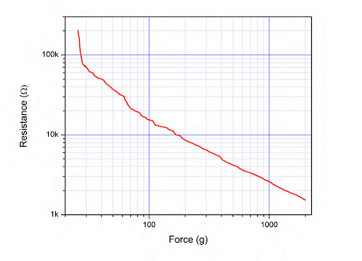
This resistance can then be correlated to force. Figure 2 shows the resistance vs force curve. Please note the logarithmic scale, however, the relationship is generally linear above 50g.
Wiring
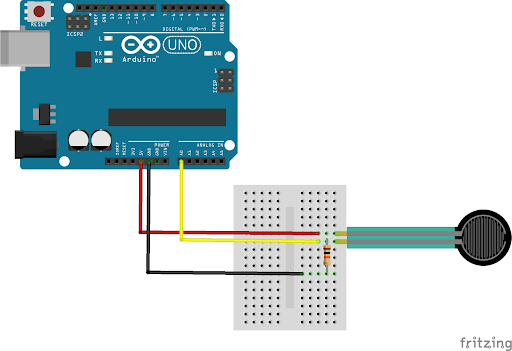
Note: The 10kresistor is essential for using the FSR (Figure 3). Do not leave it out of the circuit,
Code
As the FSR provides an analog signal, analogRead() will be used to get the voltage reading from the resistor (Figure 4).
This voltage reading can then be correlated to various levels of pressure. Here are the threshold values for the below example code.
Table 1: Threshold Values of FSR
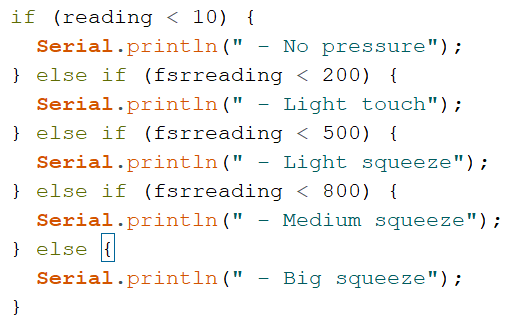
Threshold Value Pressure Reading <10 No pressure Between 10 and 200 Light touch Between 200 and 500 Light squeeze Between 500 and 800 Medium squeeze Above 800 Big squeeze
It is recommended to test the sensor in order to determine the correct threshold for your FSR. Figure 5 below outlines a block of code that will print feedback based off of how much force the sensor is experiencing.
The above code works for general correlations of resistance and pressure. If you would like to measure exact values of force, SparkFun provides a good sample code for converting the FSR reading into exact values.
Muscle Sensor
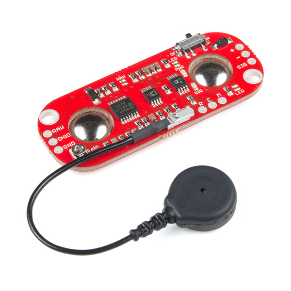
EG1004 provides a Myoware muscle sensor which uses electromyography (EMG) to measure muscle activity. This electrical activity is then converted into a varying voltage which can be read using an Arduino (Figure 1).
Downloads
Fritzing files for the muscle sensor are not publicly available. EG1004 provides a Fritzing file here.
Wiring
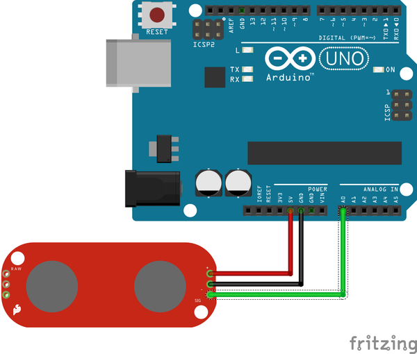
To use the muscle sensor, connect its electrodes to the snap connectors on the sensor board. Electrodes are electrical conductors used so electricity can enter or leave a nonmetallic object or part of a circuit. They do not come included with the muscle sensor, but EG1004 provides the muscle sensor electrodes. Figure 2 depicts the circuit diagram used to to connect the sensor to the Arduino.
Pins
- +: 5V
- -: Ground
- Sig: A0 (or any analog pin)
Code
As the Myoware Muscle Sensor is an analog sensor, analogRead() will be used to get the analog voltage reading from the sensor (Figure 3).
To see the value read by the sensor, use a print statement in the loop area of your code. Make sure to initialize the serial monitor by including Serial.begin(9600) in the setup area of your code (Figure 4).
Sensor values will differ depending on the placement of the electrodes (more information on electrode placement can be found ). It’s recommended to test the sensor multiple times to determine the different muscle values for your sensor.
Sensor values will differ depending on the placement of the electrodes (more information on electrode placement can be found here). The sensor should be tested multiple times to determine the different muscle values for the sensor.
Ultrasonic Sensor
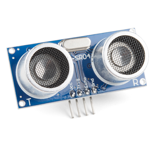
EG1004 provides an HC-SR04 Ultrasonic sensor (Figure 1). This sensor uses a process similar to echolocation in order to determine how far away an object is.
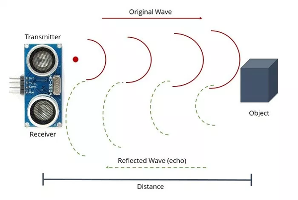
The sensor transmits a high frequency signal, then it receives the signal after it gets reflected by the object. The sensor determines the time elapsed between transmission and reception. This can be used to calculate the distance from the sensor to the object using the speed of sound (343.00 m/s).
- Ranging Distance: 2cm to 400cm
- Measuring Angle: 15.00°
- Power Supply: 5.00V
Wiring
Pins
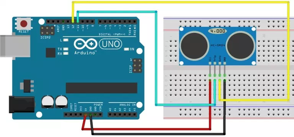
- VCC: 5.00V
- Trig: 11 or any digital pin
- Echo: 12 or any digital pin
- GND: Ground
Code
The first step in using an HC-SR04 is to set up the trigger and echo pins (Figure 4). In the setup() function, The trigger pin should be set to OUTPUT, and the echo pin should be set to INPUT as shown below. Here trigPin corresponds to the digital pin for the Trigger, while echoPin corresponds to the digital pin for the Echo.
Code can now be written in the loop() function to collect data (Figure 5). The ultrasonic sensor first needs to send a HIGH pulse of 10 or more microseconds using the trigger pin. One LOW pulse is used before to ensure a clean HIGH pulse, and another LOW after stops the HIGH pulse.
After the initial pulse has been sent out, the echo pin is then used to read the signal from the sensor (Figure 6). The method pulseIn() will return the time (in microseconds) from when the Trigger pin sends the ping, to when it is received by the Echo pin.
After reading the duration, the last step needed is to convert this to distance. Duration can be converted to centimeters using the following formula (1):
Distance (cm) = (Duration (microseconds) /2) / 29.1 (1)
Below is an example of coding this formula, in order to get the distance between the sensor and a detected object (Figure 7).
