Difference between revisions of "Introduction to Revit"
| (16 intermediate revisions by 4 users not shown) | |||
| Line 1: | Line 1: | ||
= Objective = | = Objective = | ||
The goal of this exercise is to design a | The goal of this exercise is to design a furnished apartment using Autodesk Revit. | ||
= Overview = | == Overview == | ||
Autodesk Revit is a Building Information Modeling (BIM) software for architects, structural engineers, building engineers, designers, and contractors. The software allows users to design a building and its components and share information about the design. This allows for efficient planning, design, and construction of buildings and other infrastructure. | |||
To explore the Autodesk Revit platform, consider the following prompt: | To explore the Autodesk Revit platform, consider the following prompt: | ||
A design firm has contracted with New York City’s Department of Housing Preservation and Development to create new affordable housing units for the city's residents. The firm has decided to model | A design firm has contracted with New York City’s Department of Housing Preservation and Development to create new affordable housing units for the city's residents. The firm has decided to model the units in Autodesk Revit for approval. | ||
Each unit in the apartment building must have the following specifications: | |||
*A 350-400 ft<sup>2</sup> floor plan layout of the entire apartment | *A 350-400 ft<sup>2</sup> floor plan layout of the entire apartment | ||
*A bathroom with applicable furnishings, such as a shower, toilet, and sink | *A bathroom with applicable furnishings, such as a shower, toilet, and sink | ||
*A bedroom with applicable furnishings, such as a bed, table, and desk | *A bedroom with applicable furnishings, such as a bed, table, and desk | ||
*A kitchen with applicable furnishings | *A kitchen with applicable furnishings | ||
*The apartment should be fitted with an entrance and windows | |||
== Design | === Design Considerations === | ||
*Maximize the living space in the apartment | *Maximize the living space in the apartment | ||
* | *Create a creative and coherent space | ||
*Make the apartment comfortable | *Make the apartment comfortable | ||
*The | *The apartment does not have to be rectangular | ||
= Procedure = | == Procedure == | ||
# Sketch a solution to the design considerations have the sketch approved by a TA '''before''' opening Revit. | # Sketch a solution to the design considerations have the sketch approved by a TA '''before''' opening Revit. | ||
# Open Revit | # Open Revit 2025. <span style="color:red">It's crucial to use the most up to date version!</span> Select <b>New</b>, then select <b>Imperial Multi-discipline</b> (Figure 1).[[File:Revit_2022.png|600px|thumb|center|Figure 1: Revit 2025]] | ||
# There are four major sections used to create and modify a design in Revit. The '''Quick Access Toolbar''' is highlighted in red, the '''Project Ribbon''' is highlighted in yellow, the '''Properties''' panel is highlighted in green, and the '''Project Browser''' panel is highlighted in blue (Figure 2). If any of the sections are accidentally removed from view, they can be reinserted by going to '''View → User Interface''' (rightmost icon) in the ribbon.[[File:Revit_Interface.png|500px|thumb|center|Figure 2: Revit Interface]] | # There are four major sections used to create and modify a design in Revit. The '''Quick Access Toolbar''' is highlighted in red, the '''Project Ribbon''' is highlighted in yellow, the '''Properties''' panel is highlighted in green, and the '''Project Browser''' panel is highlighted in blue (Figure 2). If any of the sections are accidentally removed from view, they can be reinserted by going to '''View → User Interface''' (rightmost icon) in the ribbon.[[File:Revit_Interface.png|500px|thumb|center|Figure 2: Revit Interface]] | ||
# Ensure the '''Properties''' panel is open by right-clicking the project workspace and clicking on '''Properties'''. If the Properties panel is not visible, select '''View''' in the '''Project Ribbon''', select '''User Interface''', and ensure the project browser is selected. | # Ensure the '''Properties''' panel is open by right-clicking the project workspace and clicking on '''Properties'''. If the Properties panel is not visible, select '''View''' in the '''Project Ribbon''', select '''User Interface''', and ensure the project browser is selected. | ||
| Line 34: | Line 34: | ||
# Select the '''Level 1''' floor plan in the '''Project Browser''' on the left side of the window by double-clicking on '''Level 1''' under '''Floor Plans'''. | # Select the '''Level 1''' floor plan in the '''Project Browser''' on the left side of the window by double-clicking on '''Level 1''' under '''Floor Plans'''. | ||
# Create the exterior walls by going to the <b>Architecture</b> tab in the ribbon and selecting '''Wall''' (Figure 4). [[File:Lab 4 Figure 26.PNG|600px|thumb|center|Figure 4: Wall Tool]] | # Create the exterior walls by going to the <b>Architecture</b> tab in the ribbon and selecting '''Wall''' (Figure 4). [[File:Lab 4 Figure 26.PNG|600px|thumb|center|Figure 4: Wall Tool]] | ||
# Make sure the walls are 8 in thick (Generic 8")and 10 ft high (Unconnected Height 10'). The thickness and height of the walls can be | # Make sure the walls are 8 in thick (Generic 8")and 10 ft high (Unconnected Height 10'). The thickness and height of the walls can be adjusted in the <b>Properties</b> panel (Figure 5). [[File:Wall properties.png|200px|thumb|center|Figure 5: Wall Properties]] | ||
## The <b>Base Constraint</b> changes where the bottom of the wall is placed in reference to the different levels. | ## The <b>Base Constraint</b> changes where the bottom of the wall is placed in reference to the different levels. | ||
## The <b>Base Offset</b> adjusts the height difference between the level and the base of the wall. | ## The <b>Base Offset</b> adjusts the height difference between the level and the base of the wall. | ||
| Line 42: | Line 42: | ||
# Insert the floor by using the <b>Floor</b> tool in the '''Architecture''' tab of the ribbon and selecting the boundary where the floor will be placed. The boundary can be made by selecting the walls or by creating individual lines using <b>Modify | Create Floor Boundary → Draw</b> on the <b>Project</b> ribbon (Figure 7). To complete the floor, click on the green checkmark in the ribbon. [[File:Create_Floor_Boundary.png|589px|thumb|center|Figure 7: Create Floor Boundary]] | # Insert the floor by using the <b>Floor</b> tool in the '''Architecture''' tab of the ribbon and selecting the boundary where the floor will be placed. The boundary can be made by selecting the walls or by creating individual lines using <b>Modify | Create Floor Boundary → Draw</b> on the <b>Project</b> ribbon (Figure 7). To complete the floor, click on the green checkmark in the ribbon. [[File:Create_Floor_Boundary.png|589px|thumb|center|Figure 7: Create Floor Boundary]] | ||
# Insert doors and windows in the apartment. Go to <b>Insert</b> → <b>Load Family</b> → <b>Doors/Windows</b> for a wide range of doors and windows (Figure 8). Doors should be 3 ft wide and 7 ft tall (No specifications for windows).[[File:Load_Family_Tool.png|600px|thumb|center|Figure 8: Load Family Tool]] | # Insert doors and windows in the apartment. Go to <b>Insert</b> → <b>Load Family</b> → <b>Doors/Windows</b> for a wide range of doors and windows (Figure 8). Doors should be 3 ft wide and 7 ft tall (No specifications for windows).[[File:Load_Family_Tool.png|600px|thumb|center|Figure 8: Load Family Tool]] | ||
# Go back to the <b>Architecture</b> tab of the ribbon and select '''Door/Window''' (Figure 9) and select the loaded door/window from the <b>Properties</b> panel. They can then be placed by clicking in the floor plan[[File: | # Go back to the <b>Architecture</b> tab of the ribbon and select '''Door/Window''' (Figure 9) and select the loaded door/window from the <b>Properties</b> panel. They can then be placed by clicking in the floor plan[[File:Load_Family_Tool.png|600px|thumb|center|Figure 9: Door and Window Tools]] | ||
# Once placed, the direction of the doors and windows can be changed with the paired arrows (Figure 10).[[File:Lab 4 Figure 32.PNG|600px|thumb|center|Figure 10: Door Direction Change]] | # Once placed, the direction of the doors and windows can be changed with the paired arrows (Figure 10).[[File:Lab 4 Figure 32.PNG|600px|thumb|center|Figure 10: Door Direction Change]] | ||
# When loading furniture or appliances, go to the <b>Architecture</b> tab of the ribbon and select <b>Component</b> → <b>Place a Component</b> (or type CM). | # When loading furniture or appliances, go to the <b>Architecture</b> tab of the ribbon and select <b>Component</b> → <b>Place a Component</b> (or type CM). | ||
| Line 79: | Line 79: | ||
|} | |} | ||
<ol start="15"> | <ol start="15"> | ||
<li> Add furniture to the floor plan. The components can be rotated before being placed by pressing the | <li> Add furniture to the floor plan. The components can be rotated before being placed by pressing the spacebar. </li> | ||
<li> Once the families are loaded, they can be placed by going to <b>Component</b> → <b>Place a Component</b> in the <b>Architecture</b> tab of the ribbon and by switching in the <b>Properties</b> tab (Figure 11). [[File:Changing_Component_Families.png|600px|thumb|center|Figure 11: Changing Component Families]] </li> | <li> Once the families are loaded, they can be placed by going to <b>Component</b> → <b>Place a Component</b> in the <b>Architecture</b> tab of the ribbon and by switching in the <b>Properties</b> tab (Figure 11). [[File:Changing_Component_Families.png|600px|thumb|center|Figure 11: Changing Component Families]] </li> | ||
<li> To insert a ceiling or ceiling appliance, select the '''Ceiling Plans''' in the <b>Project Browser</b>. Go to '''Level 1''' in the <b>Ceiling Plans</b> (Figure 12). [[File:Ceiling_Plans.png|600px|thumb|center|Figure 12: Ceiling Plans]] </li> | <li> To insert a ceiling or ceiling appliance, select the '''Ceiling Plans''' in the <b>Project Browser</b>. Go to '''Level 1''' in the <b>Ceiling Plans</b> (Figure 12). [[File:Ceiling_Plans.png|600px|thumb|center|Figure 12: Ceiling Plans]] </li> | ||
| Line 100: | Line 100: | ||
|} | |} | ||
<ol start="21"> | <ol start="21"> | ||
<li> For ceiling lights, go back to the '''Level 1 Ceiling Plan''' in the '''Project Browser'''. Select the lights that are to be placed with the '''Component''' tool in the <b>Architecture</b> tab. Once the lighting fixture is selected, select <b>Modify | Place Component</b> → <b>Placement</b> → <b>Place on Face</b> tab of the ribbon to place the lights on the ceiling (Figure 15). [[File:Place_on_Face_Tool.png| | <li> For ceiling lights, go back to the '''Level 1 Ceiling Plan''' in the '''Project Browser'''. Select the lights that are to be placed with the '''Component''' tool in the <b>Architecture</b> tab. Once the lighting fixture is selected, select <b>Modify | Place Component</b> → <b>Placement</b> → <b>Place on Face</b> tab of the ribbon to place the lights on the ceiling (Figure 15). [[File:Place_on_Face_Tool.png|430px|thumb|center|Figure 15: Place on Face Tool]] </li> | ||
<li> In the <b>Quick Access Toolbar</b>, select <b>Default 3D View</b> (small house icon) to view the project in 3D (Figure 16). [[File:Default_3D_View_Tool_.png|600px|thumb|center|Figure 16: Default 3D View Tool]] </li> | <li> In the <b>Quick Access Toolbar</b>, select <b>Default 3D View</b> (small house icon) to view the project in 3D (Figure 16). [[File:Default_3D_View_Tool_.png|600px|thumb|center|Figure 16: Default 3D View Tool]] </li> | ||
<li> Save the file as an Autodesk Revit File (RVT) file. Submit the RVT file on the EG1004 website by 11:59 PM the night before the next lab. | <li> Save the file as an Autodesk Revit File (RVT) file. Submit the RVT file on the EG1004 website by 11:59 PM the night before the next lab. | ||
</ol> | </ol> | ||
= Assignment = | == Assignment == | ||
== File Submission == | === File Submission === | ||
The RVT file must be submitted to the [https://eg.poly.edu/submit.php EG1004 website] by 11:59 PM the night | There is no individual lab report or team presentation for this lab. The RVT file and [https://docs.google.com/document/d/1v0ojKQ_j7qIYh9rDMHyZc75gHocSlXBwlPl1x4MDvH0/edit?usp=sharing ideation assignment] must be submitted to the [https://eg.poly.edu/submit.php EG1004 website] by 11:59:59 PM the night of the lab session. | ||
Latest revision as of 16:47, 27 January 2025
Objective
The goal of this exercise is to design a furnished apartment using Autodesk Revit.
Overview
Autodesk Revit is a Building Information Modeling (BIM) software for architects, structural engineers, building engineers, designers, and contractors. The software allows users to design a building and its components and share information about the design. This allows for efficient planning, design, and construction of buildings and other infrastructure.
To explore the Autodesk Revit platform, consider the following prompt:
A design firm has contracted with New York City’s Department of Housing Preservation and Development to create new affordable housing units for the city's residents. The firm has decided to model the units in Autodesk Revit for approval.
Each unit in the apartment building must have the following specifications:
- A 350-400 ft2 floor plan layout of the entire apartment
- A bathroom with applicable furnishings, such as a shower, toilet, and sink
- A bedroom with applicable furnishings, such as a bed, table, and desk
- A kitchen with applicable furnishings
- The apartment should be fitted with an entrance and windows
Design Considerations
- Maximize the living space in the apartment
- Create a creative and coherent space
- Make the apartment comfortable
- The apartment does not have to be rectangular
Procedure
- Sketch a solution to the design considerations have the sketch approved by a TA before opening Revit.
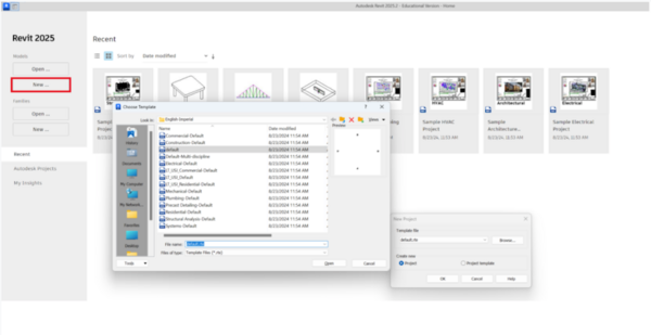
- Open Revit 2025. It's crucial to use the most up to date version! Select New, then select Imperial Multi-discipline (Figure 1).
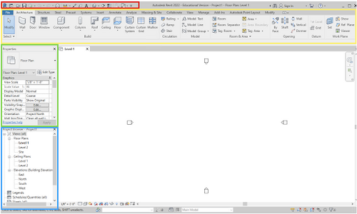
- There are four major sections used to create and modify a design in Revit. The Quick Access Toolbar is highlighted in red, the Project Ribbon is highlighted in yellow, the Properties panel is highlighted in green, and the Project Browser panel is highlighted in blue (Figure 2). If any of the sections are accidentally removed from view, they can be reinserted by going to View → User Interface (rightmost icon) in the ribbon.
- Ensure the Properties panel is open by right-clicking the project workspace and clicking on Properties. If the Properties panel is not visible, select View in the Project Ribbon, select User Interface, and ensure the project browser is selected.
- In the ribbon, go to the Manage tab and select Project Units (or type UN) under the Settings section (Figure 3). Click the Length value and select Feet and fractional inches with rounding to the nearest 1/32 in. Click OK.
- Ensure the Properties panel is open by right-clicking anywhere and clicking on Properties.
- Select the Level 1 floor plan in the Project Browser on the left side of the window by double-clicking on Level 1 under Floor Plans.
- Create the exterior walls by going to the Architecture tab in the ribbon and selecting Wall (Figure 4).
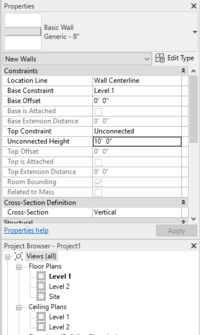
- Make sure the walls are 8 in thick (Generic 8")and 10 ft high (Unconnected Height 10'). The thickness and height of the walls can be adjusted in the Properties panel (Figure 5).
- The Base Constraint changes where the bottom of the wall is placed in reference to the different levels.
- The Base Offset adjusts the height difference between the level and the base of the wall.
- The Top Constraint determines where the top of the wall is located. If the top constraint is unconnected, then the Unconnected Height can be used to determine a numerical value for the height of the wall.
- Outline the design with the exterior walls and ensure the total area is between 350-400 ft2 before moving on.
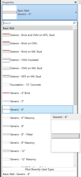
- Insert the interior walls (6 in thick and 10 ft high) within the walls for the bathroom and any other walls. The thickness of the wall can be changed in the drop-down menu in the Properties panel (Figure 6).
- Insert the floor by using the Floor tool in the Architecture tab of the ribbon and selecting the boundary where the floor will be placed. The boundary can be made by selecting the walls or by creating individual lines using Modify | Create Floor Boundary → Draw on the Project ribbon (Figure 7). To complete the floor, click on the green checkmark in the ribbon.
- Insert doors and windows in the apartment. Go to Insert → Load Family → Doors/Windows for a wide range of doors and windows (Figure 8). Doors should be 3 ft wide and 7 ft tall (No specifications for windows).
- Go back to the Architecture tab of the ribbon and select Door/Window (Figure 9) and select the loaded door/window from the Properties panel. They can then be placed by clicking in the floor plan
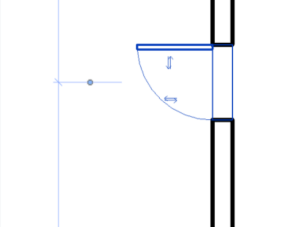
- Once placed, the direction of the doors and windows can be changed with the paired arrows (Figure 10).
- When loading furniture or appliances, go to the Architecture tab of the ribbon and select Component → Place a Component (or type CM).
- Furniture and appliances can be added with the Load Family tool. Only the furniture and appliances from the specifications must be in the floor plan. Table 1 shows the File Paths for all the files needed in this lab. In the dialog that appears, the material in the Override column should be changed.
Table 1: File Paths for all Furniture Components File Paths Sink English → Plumbing → MEP → Fixtures → Sinks Toilet English → Plumbing → MEP → Fixtures → Water Closets Shower English → Plumbing → MEP → Fixtures → Shower Bed English → Furniture → Beds Kitchenette English → Specialty Equipment → Domestic Table English → Furniture → Tables Desk English → Furniture → Tables Door English → Door → Residential
- Add furniture to the floor plan. The components can be rotated before being placed by pressing the spacebar.
- Once the families are loaded, they can be placed by going to Component → Place a Component in the Architecture tab of the ribbon and by switching in the Properties tab (Figure 11).
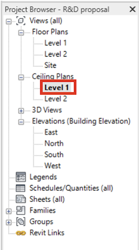
- To insert a ceiling or ceiling appliance, select the Ceiling Plans in the Project Browser. Go to Level 1 in the Ceiling Plans (Figure 12).
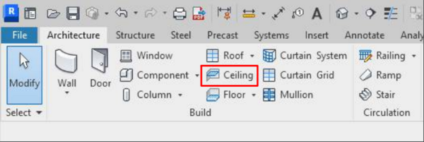
- Use the Ceiling tool in the Architecture tab of the ribbon to create the ceiling (Figure 13).
- The ceiling is created with the same method as the floor, by selecting a boundary where the ceiling will be placed. The individual walls can be selected to create the boundary by creating a Sketch Ceiling tool, or entire areas can be selected for the boundary using the Automatic Ceiling (Figure 14). Complete the ceiling by clicking the green checkmark in the ribbon.
- Navigate back to the Level 1 floor plan in the Project Browser. Insert the electrical appliances in the apartment using Architecture → Component on the ribbon and using the File Paths provided in Table 2.
Table 2: File Paths for Electrical Components Components File Paths Light Switch US Imperial → Electrical → MEP → Electric Power → Terminals → Lighting Switches Ceiling Light US Imperial → Lighting → MEP → Internal
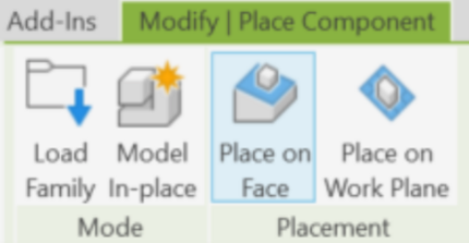
- For ceiling lights, go back to the Level 1 Ceiling Plan in the Project Browser. Select the lights that are to be placed with the Component tool in the Architecture tab. Once the lighting fixture is selected, select Modify | Place Component → Placement → Place on Face tab of the ribbon to place the lights on the ceiling (Figure 15).
- In the Quick Access Toolbar, select Default 3D View (small house icon) to view the project in 3D (Figure 16).
- Save the file as an Autodesk Revit File (RVT) file. Submit the RVT file on the EG1004 website by 11:59 PM the night before the next lab.
Assignment
File Submission
There is no individual lab report or team presentation for this lab. The RVT file and ideation assignment must be submitted to the EG1004 website by 11:59:59 PM the night of the lab session.
