Difference between revisions of "Digital Multimeters Guidelines"
From EG1004 Lab Manual
| (2 intermediate revisions by 2 users not shown) | |||
| Line 1: | Line 1: | ||
A multimeter is a common engineering lab tool that allows engineers to test electrical components. Its common uses include measuring current, voltage, resistance, and how charged a capacitor is. | |||
= Multimeter Lead Wires = | = Multimeter Lead Wires = | ||
* To ensure the right values are being read attach the lead wires to the | * To ensure the right values are being read attach the lead wires to the correct port of the multimeter. | ||
* Only the red wire switches ports depending on what is being measured and the type of multimeter. | * Only the red wire switches ports depending on what is being measured and the type of multimeter. | ||
* In the Multimeter shown in Figure 1, while determining the voltage red lead wire will be in port 4 and when determining the current the red lead will be in | * In the Multimeter shown in Figure 1, while determining the voltage the red lead wire will be in port 4 and when determining the current the red lead will be in ports 1 or 2, depending on the current source. Utilize port 1 or the 10.00 A port in this case. | ||
[[File:Ports_on_a_Multimeter.jpg|475px|thumb|center|Figure 1: Ports on a Multimeter]] | [[File:Ports_on_a_Multimeter.jpg|475px|thumb|center|Figure 1: Ports on a Multimeter]] | ||
| Line 14: | Line 11: | ||
= Testing the Multimeter = | = Testing the Multimeter = | ||
* To test the functionality of the multimeter, test the continuity. The leads | * To test the functionality of the multimeter, test the continuity. The leads do not have to be in a specific orientation to test the continuity. | ||
* The continuity can be tested by shifting the dial to the continuity setting shown in Figure 2. | * The continuity can be tested by shifting the dial to the continuity setting shown in Figure 2. | ||
[[File:Continuity_symbol_on_a_Multimeter.png|300px|thumb|center|Figure 2: Continuity | [[File:Continuity_symbol_on_a_Multimeter.png|300px|thumb|center|Figure 2: Continuity Symbol on a Multimeter]] | ||
* After the dial is in the continuity setting touch the two leads of the meter together. If there is a sound | * After the dial is in the continuity setting touch the two leads of the meter together. If there is a sound, then the multimeter is working. If there is no sound, then the multimeter is not functional. | ||
= Measuring Voltage = | = Measuring Voltage = | ||
Measure the voltage in parallel. Measuring voltage in series will result in the output from multimeter to be 0.00 V. | |||
# Connect the leads of the multimeter in parallel to the load in the circuit. The connection shown in Figure 3. [[Image:Multimeter in Parallel.png|thumb|362px|center|Figure 3: Multimeter in a Parallel | # Connect the leads of the multimeter in parallel to the load in the circuit. The connection is shown in Figure 3. [[Image:Multimeter in Parallel.png|thumb|362px|center|Figure 3: Multimeter in a Parallel Circuit with the Load]] | ||
# If the voltage shows a negative value | # If the voltage shows a negative value then the lead wire orientation is reversed within a circuit. The negative voltage does not affect the data, since it should be viewed as an absolute value. The negative value means the polarity is switched. | ||
# Turn the dial to the specific range of voltage shown in Figure 4, to get the proper value. | # Turn the dial to the specific range of voltage shown in Figure 4, to get the proper value. Fore example, to read a voltage under 2000.00 mV select 2000, and change accordingly. | ||
[[File:Multimeter_dial_and_values.jpg|500px|thumb|center|Figure 4: Multimeter dial and values]] | [[File:Multimeter_dial_and_values.jpg|500px|thumb|center|Figure 4: Multimeter dial and values]] | ||
= Measuring Current = | = Measuring Current = | ||
Measure current in series. | |||
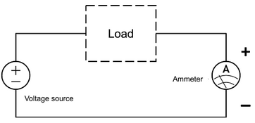
# To measure current, connect the multimeter in series with the load,as shown in Figure 5.[[Image:Multimeter in Series.png|thumb|362px|center|Figure 5: Multimeter in a Series circuit with the Load]] | |||
# To measure current, connect the multimeter in series with the load, shown in Figure 5.[[Image:Multimeter in Series.png|thumb|362px|center|Figure 5: Multimeter in a Series circuit with the | |||
# Select the proper current and adjust the dial accordingly, refer to Figure 4. | # Select the proper current and adjust the dial accordingly, refer to Figure 4. | ||
| Line 43: | Line 39: | ||
# If the multimeter makes noise, that means that the capacitor is shorted and is not functional. | # If the multimeter makes noise, that means that the capacitor is shorted and is not functional. | ||
= Checking if the | = Checking if the capacitor is fully charged = | ||
# To | # To check if the capacitor is fully charged, the current across the capacitors over time should be checked. | ||
# The | # The multimeter must be in series with the capacitor to check the current across the multimeter over time. | ||
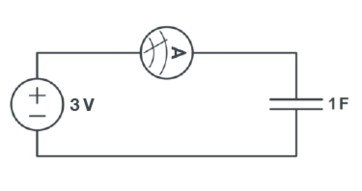
#If there are two capacitors, then both | #If there are two capacitors, then both capacitors must be in series with the power source and the multimeter, to test if the capacitors are fully charged. Following is an example of a one capacitor based circuit to test if it’s fully charged.[[Image:Lab 10 Figure 8.png|thumb|362px|center|Figure 6: The circuit for measuring current across a capacitor]] | ||
# When the value of the current shown on the multimeter approaches | # When the value of the current shown on the multimeter approaches 0.00 A, the capacitor is fully charged. | ||
Latest revision as of 05:06, 2 September 2024
A multimeter is a common engineering lab tool that allows engineers to test electrical components. Its common uses include measuring current, voltage, resistance, and how charged a capacitor is.
Multimeter Lead Wires
- To ensure the right values are being read attach the lead wires to the correct port of the multimeter.
- Only the red wire switches ports depending on what is being measured and the type of multimeter.
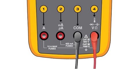
- In the Multimeter shown in Figure 1, while determining the voltage the red lead wire will be in port 4 and when determining the current the red lead will be in ports 1 or 2, depending on the current source. Utilize port 1 or the 10.00 A port in this case.
Testing the Multimeter
- To test the functionality of the multimeter, test the continuity. The leads do not have to be in a specific orientation to test the continuity.
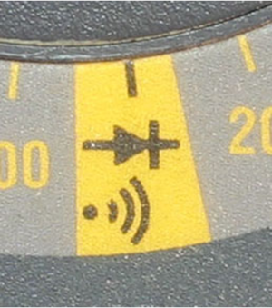
- The continuity can be tested by shifting the dial to the continuity setting shown in Figure 2.
- After the dial is in the continuity setting touch the two leads of the meter together. If there is a sound, then the multimeter is working. If there is no sound, then the multimeter is not functional.
Measuring Voltage
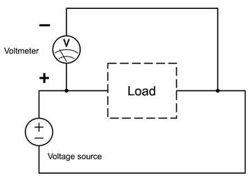
Measure the voltage in parallel. Measuring voltage in series will result in the output from multimeter to be 0.00 V.
- Connect the leads of the multimeter in parallel to the load in the circuit. The connection is shown in Figure 3.
- If the voltage shows a negative value then the lead wire orientation is reversed within a circuit. The negative voltage does not affect the data, since it should be viewed as an absolute value. The negative value means the polarity is switched.
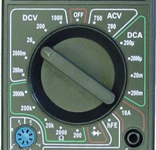
- Turn the dial to the specific range of voltage shown in Figure 4, to get the proper value. Fore example, to read a voltage under 2000.00 mV select 2000, and change accordingly.
Measuring Current
Measure current in series.
- To measure current, connect the multimeter in series with the load,as shown in Figure 5.
- Select the proper current and adjust the dial accordingly, refer to Figure 4.
Testing Capacitors
- To test the capacitors, place the dial into the continuity setting of the multimeter.
- Touch the leads from the multimeter to lead of the capacitor.
- If the multimeter makes noise, that means that the capacitor is shorted and is not functional.
Checking if the capacitor is fully charged
- To check if the capacitor is fully charged, the current across the capacitors over time should be checked.
- The multimeter must be in series with the capacitor to check the current across the multimeter over time.
- If there are two capacitors, then both capacitors must be in series with the power source and the multimeter, to test if the capacitors are fully charged. Following is an example of a one capacitor based circuit to test if it’s fully charged.
- When the value of the current shown on the multimeter approaches 0.00 A, the capacitor is fully charged.
