Difference between revisions of "VEX CAD Assembly Guide"
| Line 34: | Line 34: | ||
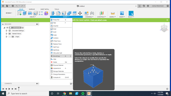
# Move the two bodies being aligned close to one another using the Move/Copy tool (Figure 3)[[File:VEX_CAD_Assembly_Guide_media_2.png|600px|thumb|center|Figure 3: Move/Copy Tool]] | # Move the two bodies being aligned close to one another using the Move/Copy tool (Figure 3)[[File:VEX_CAD_Assembly_Guide_media_2.png|600px|thumb|center|Figure 3: Move/Copy Tool]] | ||
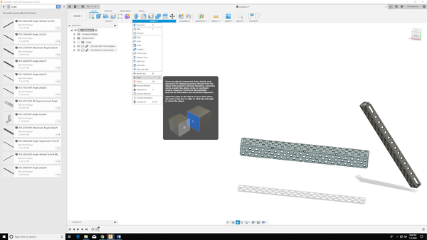
# Under the Modify section of the toolbar, select the Align tool (Figure 4) [[File:VEX_CAD_Assembly_Guide_media_4.png|600px|thumb|center|Figure 4: Align Tool]] | # Under the Modify section of the toolbar, select the Align tool (Figure 4) [[File:VEX_CAD_Assembly_Guide_media_4.png|600px|thumb|center|Figure 4: Align Tool]] | ||
# The Align dialog will appear on the right side of the window (Figure 5). For the From profile, select the first surface, edge, or point being aligned. For the To profile, select the second surface, edge, or point. The first profile will become aligned to the second profile [[File: | # The Align dialog will appear on the right side of the window (Figure 5). For the From profile, select the first surface, edge, or point being aligned. For the To profile, select the second surface, edge, or point. The first profile will become aligned to the second profile [[File:Align_box.jpg|600px|thumb|center|Figure 5: Align Dialog]] | ||
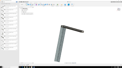
# Repeat steps 1 - 3 using different points on the bodies being aligned until they are oriented as desired (Figure 6). Make sure the bodies are aligned as desired in the x-, y-, and z-directions [[File:VEX_CAD_Assembly_Guide_media_5.png|600px|thumb|center|Figure 6: Aligned Bodies]] | # Repeat steps 1 - 3 using different points on the bodies being aligned until they are oriented as desired (Figure 6). Make sure the bodies are aligned as desired in the x-, y-, and z-directions [[File:VEX_CAD_Assembly_Guide_media_5.png|600px|thumb|center|Figure 6: Aligned Bodies]] | ||
Revision as of 02:44, 5 February 2020
Goals for this Guide
- Be able to troubleshoot common CAD problems
- Design and implement CAD drawings in Fusion 360 for a VEX robot
Disclaimer
Please thoroughly read the entire guide before starting your Fusion 360 assembly. There are some tips that will make creating your model much easier. Also, keep in mind it might take more than three Aligns to get your parts to snap into place at first, but once you complete a few and start to become comfortable with it, it should become faster. If you have any questions, feel free to ask a TA.
Preparation of Software
Invite to Collaborate in Fusion 360
- Download Fusion 360 from the Autodesk website
- Create an account with your NYU email or sign in
- Once downloaded, open Fusion 360
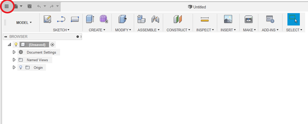
- In the top left corner of the window, click the Data Panel icon (Figure 1)
- In the Data Panel, click New Project. Name your project and press the Enter key
- Double click on the box with your project name. Go to the People tab at the top of the page
- Enter the email addresses of your teammates and click the Invite button
Download and Import VEX Parts
- Download the Autodesk VEX Kit of Parts (KoP). Make sure to download the Fusion 360 KoP for VEX EDR
- Extract the downloaded ZIP folder (Figure 2)
- In Fusion 360, go to the Data tab of your project and click New Folder. Name the new folder and press the Enter key. This folder will contain all the downloaded VEX parts for the project
- Double click the new folder that was just created. Click the Upload button
- In the dialog that just appeared, click Select Files
- In the File Explorer, navigate to the unzipped folder of VEX parts
- For Mac users, select the _MACOSX folder. For Windows users, select the Fusion_360_VEX_EDR_KOP folder. Select all the individual F3Z files in each folder to download. You can select all the F3Z files in individual folders but cannot select F3Z files from different folders. Select the files you believe you will need for your project. Click Open
- In the window that appears, click Upload
- The VEX parts will take a few minutes to upload from your files to Fusion 360. Once the upload is complete, click Close in the Job Status window. There should be new files in the Data Panel. You can double click one of the files to open the VEX part, or click and drag the files into your project to use them for the assembly
Creating the Assembly
In CAD, an assembly is a group of individual components that are aligned to each other using mating conditions. Mating conditions are definitions for the relative positions of components in respect to each other. Individual components usually require multiple mating conditions to become fully defined in 3D space. The general purpose of assemblies is to visualize how components become geometrically constrained in a system, and how these geometric constraints allow engineers to simulate, analyze, and evaluate their designs as to mimic real-life conditions. In Fusion 360, there are a few functions to generate mating conditions for assemblies. This guide will specifically cover the Align tool, Joint tool, and Rigid Group tool. Note: "Connecting pieces" are screws, rods, shaft collars, wheels, etc.
Align Tool
The Align tool aligns the geometry from one component to the geometry of another component. The aligned geometry can be a surface, edge, or point. The Align tool is a simplified mating condition generator that makes all selected geometry coincident to each other.
- Move the two bodies being aligned close to one another using the Move/Copy tool (Figure 3)
- Under the Modify section of the toolbar, select the Align tool (Figure 4)
- The Align dialog will appear on the right side of the window (Figure 5). For the From profile, select the first surface, edge, or point being aligned. For the To profile, select the second surface, edge, or point. The first profile will become aligned to the second profile File:Align box.jpgFigure 5: Align Dialog
- Repeat steps 1 - 3 using different points on the bodies being aligned until they are oriented as desired (Figure 6). Make sure the bodies are aligned as desired in the x-, y-, and z-directions
Joint Tool
(Insert information here)
Rigid Group Tool
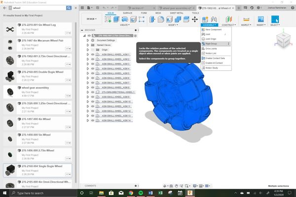
The Rigid Group tool locks the relative position of the selected components. The components are treated as a single object when moved or when joints are applied. Note that components like the wheels and motors are already sub-assemblies consisting of two or more bodies. They will have to be joined as a Rigid Group prior to being aligned with additional components.
- Select all the bodies of interest from the Browser on the left side of the window
- Go to the Assemble tab in the toolbar and select the Rigid Group tool (Figure 7). If prompted with a warning that states "some components have been moved", select Capture Position
- The Rigid Group dialog will appear on the right side of the window (Figure 8). Click OK to make the Rigid Group
Replicating Sub-Assemblies
In some instances, such as for the wheels, it will be required to align the gears of the drivetrain to the wheel before aligning the entire sub-assembly of the gears and wheel to the frame. Seeing that most designs have four wheels, repeating the process of aligning over and over can become tedious and time-consuming. Using the method below, sub-assemblies can be joined as one body and copied as many times as needed:
- Go to File > New Design in the same project as the rest of the VEX files
- Click and drag in desired components from the Data Panel
- Under the Modify tab of the toolbar, select the Align tool
- Align the components to each other
- Save the file in the same folder as all the downloaded Vex components
- Now you can drag newly made rigid group into the main robot assembly as many times as needed
Using this process whenever there are repeated components will greatly reduce the time needed to make the full assembly.
