Difference between revisions of "Sandbox/ReverseEngineering"
(This is the Reverse Engineering sections from the Product Evaluation lab.) |
m |
||
| (2 intermediate revisions by the same user not shown) | |||
| Line 1: | Line 1: | ||
= Reverse Engineering = | |||
Reverse engineering software involves reversing a program's machine code to obtain the original source code or determine the file structures the program uses. This is done when source code is lost or is not available. For example, when a project is reactivated after being dormant for years to add new features to a product, the original design documentation may have been lost. Also, when companies are writing a program that must interface with a second company's software, the second company may not have any incentive to cooperate by describing how the data in the files they use are organized, forcing the first company to deduce it on their own. Sometimes, this process is used to improve the performance of a program, to fix a bug, or to find a virus. When the source code is obtained in this way for any of these reasons, it is legal and necessary. Reverse engineering software to copy it constitutes a copy¬right violation and is illegal.<ref name="two">''What Is ''website. TechTarget Network. Retrieved July 29th, 2003.</ref> | Reverse engineering software involves reversing a program's machine code to obtain the original source code or determine the file structures the program uses. This is done when source code is lost or is not available. For example, when a project is reactivated after being dormant for years to add new features to a product, the original design documentation may have been lost. Also, when companies are writing a program that must interface with a second company's software, the second company may not have any incentive to cooperate by describing how the data in the files they use are organized, forcing the first company to deduce it on their own. Sometimes, this process is used to improve the performance of a program, to fix a bug, or to find a virus. When the source code is obtained in this way for any of these reasons, it is legal and necessary. Reverse engineering software to copy it constitutes a copy¬right violation and is illegal.<ref name="two">''What Is ''website. TechTarget Network. Retrieved July 29th, 2003.</ref> | ||
Hardware reverse engineering involves taking apart a device to see how it works. If a processor manufacturer wants to see how a competitor's processor works, the company can purchase the processor, disassemble it, and then make a new processor similar to it. In some countries, this process is illegal. Hardware reverse engineering is quite expensive and requires an expert in the field.<ref name="two"></ref> | Hardware reverse engineering involves taking apart a device to see how it works. If a processor manufacturer wants to see how a competitor's processor works, the company can purchase the processor, disassemble it, and then make a new processor similar to it. In some countries, this process is illegal. Hardware reverse engineering is quite expensive and requires an expert in the field.<ref name="two"></ref> | ||
== | = Gear Trains = | ||
When beginning the process of reverse engineering the robot, identifying the gear trains and the individual gears used in the original design and in the final design is critical to understanding the robot's operation. | |||
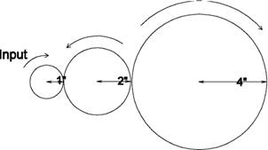
There are two types of gear trains: simple and compound. A simple gear train has its gears arranged in a line (see Figure 1). | |||
[[Image:Lab reveng 1.jpg|frame|center|Figure 1: Simple gear train.]] | |||
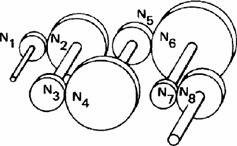
Compound gear trains use axles to connect the component gears (see Figure 2). | |||
[[Image:Lab reveng 2.jpg|frame|center|Figure 2: Compound gear train.]] | |||
Gear trains have measurable characteristics known as gear ratio and velocity ratio. These characteristics are inversely proportional. Gear ratio equals output over input, while velocity ratio equals input over output. If multiple gears are being used, the gear ratio and velocity ratio are the product of these ratios for each individual gear. To determine input and output values, engineers count the number of teeth on each gear or by measuring each gear's radius. | |||
For example, to compute the gear ratio of the gear trains in Figures 1 and 2, these formulas are used, where the values are the radii of the gears in the gear train: | |||
{| class="wikitable" style="text-align: center; margin: 0px auto;" | |||
|<math>Gear Ratio = \frac{2}{1} \times \frac{4}{2} = 4\,</math><br />Simple gear train | |||
|<math>Gear Ratio = \frac{N_2}{N_1} \times \frac{N_4}{N_3} \times \frac{N_6}{N_5} \times \frac{N_8}{N_7}\,</math><br />Compound gear train | |||
|} | |||
For example, to compute the velocity ratio of the gear trains above, these formulas are used: | |||
{| class="wikitable" style="text-align: center; margin: 0px auto;" | |||
|<math>Velocity Ratio = \frac{1}{2} \times \frac{2}{4} = \frac{1}{4}\,</math><br />Simple gear train | |||
|<math>Velocity Ratio = \frac{N_1}{N_2} \times \frac{N_3}{N_4} \times \frac{N_5}{N_6} \times \frac{N_7}{N_8}\,</math><br />Compound gear train | |||
|} | |||
It is important to note that the input is the source of rotation in a system, like a motor, and the output is the final gear of rotation in a system, like a wheel. | |||
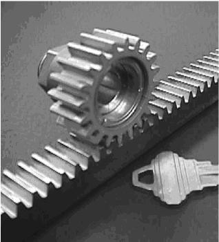
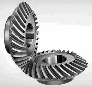
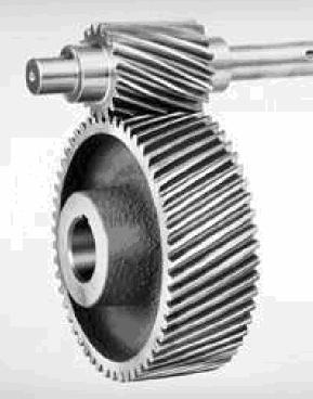
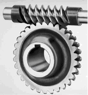
Below are images and descriptions of the types of gears that can be implemented in your robot's gear train design. | |||
{| class="wikitable" style="text-align: center; margin: 0px auto;" | |||
|[[Image:Lab reveng 7.jpg|frame|center|'''Figure 3a: Rack gear.''' Its purpose is to change rotation into linear motion.]] | |||
|[[Image:Lab reveng 8.jpg|frame|center|'''Figure 3b: Crown gear.''' Its purpose is to change the direction of rotation perpendicularly.]] | |||
|- | |||
|[[Image:Lab reveng 9.jpg|frame|center|'''Figure 3c: Spur gear.''' Its purpose is to transmit torque through the gear train.]] | |||
|[[Image:Lab reveng 10.jpg|frame|center|'''Figure 3d: Worm gear.''' Its purpose is to change the direction of rotation perpendicularly.]] | |||
|- | |||
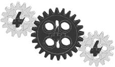
|[[Image:Lab reveng 11.jpg|frame|center|'''Figure 3e: Idler gear.''' Its purpose is to transfer force while not affecting the gear or velocity ratios.]] | |||
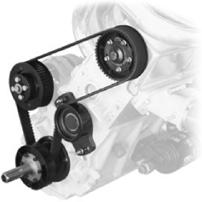
|[[Image:Lab reveng 12.jpg|frame|center|'''Figure 3f: Pulley gear.''' Its purpose is to transmit rotation from one point to one or more other points.]] | |||
|} | |||
= Center of Gravity = | |||
'''Center of Gravity''' is the place in a system or body (such as a robot) where the weight is evenly distributed and all sides are in balance. An example of the center of gravity is the middle of a seesaw when it is balanced. | |||
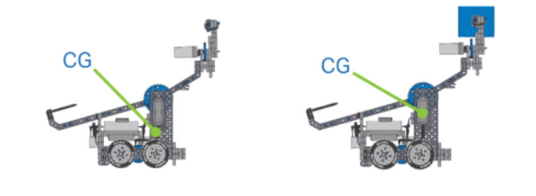
You can think of a robot’s center of gravity as the “center position” of all the weight on the robot. Because the Center of Gravity uses both weight and position, heavier objects have a greater effect than lighter ones in determining where the center of gravity is. For example, if your robot can collect, hold, and/or manipulate objects, those objects change the center of gravity as they are being manipulated because they add weight. | |||
[[Image:CofG.PNG|frame|center|Figure 4: Change of Center of Gravity because of change of weight of the robot.]] | |||
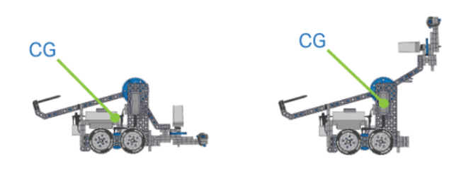
Likewise, pieces that are farther out have a greater effect than pieces that are near the middle of the robot. So, if your robot has an arm that lifts and/or reaches, it's center of gravity changes with that movement. | |||
[[Image:DynamicCG.PNG|frame|center|Figure 5: Change of Center of Gravity because of dynamic parts.]] | |||
= Drivetrain Design = | |||
The most basic, multi-functional competition robot '''Drivetrain''' design consists of: | |||
* A rectangular '''Chassis''' (the structure of a mobile robot that holds wheels, motors, and/or any other hardware used to make up a '''Drivetrain''') | |||
* Two Motors | |||
* Four Wheels | |||
* Gears transmitting Power from the Motors to all Wheels | |||
Drivetrains can come in all shapes and sizes - some don’t provide power to all wheels, use different types of wheels, or are not even a rectangular shape! Whatever the details of your Drivetrain, you should always be aware of a property known as '''Turning Scrub'''. | |||
'''Turning Scrub''' is the friction that resists turning. This friction is created from the wheels dragging sideways on the ground as a robot (or another mobile vehicle) turns. The greater the '''Turning Scrub''' in a '''Drivetrain''', the harder it is for a robot to turn. '''Turning Scrub''' in a basic '''Drivetrain''' can be easily managed and minimized in two ways: | |||
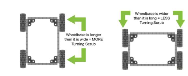
1. Make sure that the '''Wheelbase''' (distance between '''Drivetrain''' wheels) is wider (side-to-side) than it is long (front-to-back): | |||
[[Image:Wheelbase.PNG|frame|center|Figure 6: Wheelbase Example.]] | |||
2. Use different wheel and/or tire types to reduce the friction of '''Turning Scrub''': | |||
[[Image:Wheels.PNG|frame|center|Figure 7: Different Wheels Example.]] | |||
Latest revision as of 18:18, 24 August 2019
Reverse Engineering
Reverse engineering software involves reversing a program's machine code to obtain the original source code or determine the file structures the program uses. This is done when source code is lost or is not available. For example, when a project is reactivated after being dormant for years to add new features to a product, the original design documentation may have been lost. Also, when companies are writing a program that must interface with a second company's software, the second company may not have any incentive to cooperate by describing how the data in the files they use are organized, forcing the first company to deduce it on their own. Sometimes, this process is used to improve the performance of a program, to fix a bug, or to find a virus. When the source code is obtained in this way for any of these reasons, it is legal and necessary. Reverse engineering software to copy it constitutes a copy¬right violation and is illegal.[1]
Hardware reverse engineering involves taking apart a device to see how it works. If a processor manufacturer wants to see how a competitor's processor works, the company can purchase the processor, disassemble it, and then make a new processor similar to it. In some countries, this process is illegal. Hardware reverse engineering is quite expensive and requires an expert in the field.[1]
Gear Trains
When beginning the process of reverse engineering the robot, identifying the gear trains and the individual gears used in the original design and in the final design is critical to understanding the robot's operation.
There are two types of gear trains: simple and compound. A simple gear train has its gears arranged in a line (see Figure 1).
Compound gear trains use axles to connect the component gears (see Figure 2).
Gear trains have measurable characteristics known as gear ratio and velocity ratio. These characteristics are inversely proportional. Gear ratio equals output over input, while velocity ratio equals input over output. If multiple gears are being used, the gear ratio and velocity ratio are the product of these ratios for each individual gear. To determine input and output values, engineers count the number of teeth on each gear or by measuring each gear's radius.
For example, to compute the gear ratio of the gear trains in Figures 1 and 2, these formulas are used, where the values are the radii of the gears in the gear train:
Simple gear train |
Compound gear train |
For example, to compute the velocity ratio of the gear trains above, these formulas are used:
Simple gear train |
Compound gear train |
It is important to note that the input is the source of rotation in a system, like a motor, and the output is the final gear of rotation in a system, like a wheel.
Below are images and descriptions of the types of gears that can be implemented in your robot's gear train design.
Center of Gravity
Center of Gravity is the place in a system or body (such as a robot) where the weight is evenly distributed and all sides are in balance. An example of the center of gravity is the middle of a seesaw when it is balanced.
You can think of a robot’s center of gravity as the “center position” of all the weight on the robot. Because the Center of Gravity uses both weight and position, heavier objects have a greater effect than lighter ones in determining where the center of gravity is. For example, if your robot can collect, hold, and/or manipulate objects, those objects change the center of gravity as they are being manipulated because they add weight.
Likewise, pieces that are farther out have a greater effect than pieces that are near the middle of the robot. So, if your robot has an arm that lifts and/or reaches, it's center of gravity changes with that movement.
Drivetrain Design
The most basic, multi-functional competition robot Drivetrain design consists of:
- A rectangular Chassis (the structure of a mobile robot that holds wheels, motors, and/or any other hardware used to make up a Drivetrain)
- Two Motors
- Four Wheels
- Gears transmitting Power from the Motors to all Wheels
Drivetrains can come in all shapes and sizes - some don’t provide power to all wheels, use different types of wheels, or are not even a rectangular shape! Whatever the details of your Drivetrain, you should always be aware of a property known as Turning Scrub.
Turning Scrub is the friction that resists turning. This friction is created from the wheels dragging sideways on the ground as a robot (or another mobile vehicle) turns. The greater the Turning Scrub in a Drivetrain, the harder it is for a robot to turn. Turning Scrub in a basic Drivetrain can be easily managed and minimized in two ways:
1. Make sure that the Wheelbase (distance between Drivetrain wheels) is wider (side-to-side) than it is long (front-to-back):
2. Use different wheel and/or tire types to reduce the friction of Turning Scrub:
