Difference between revisions of "Sustainable Energy Vehicle Competition"
| Line 172: | Line 172: | ||
* Lemon Juice | * Lemon Juice | ||
* Metal Strips | * Metal Strips | ||
** | ** Zinc, Copper | ||
* 3 Alligator cable sets | * 3 Alligator cable sets | ||
* Standard Lego Car Chassis plus Lego parts kit | * Standard Lego Car Chassis plus Lego parts kit | ||
| Line 181: | Line 181: | ||
== Procedure == | == Procedure == | ||
Every group will be designated to test a pair of power storage devices and power sources. | |||
=== Part 1: Testing the Power Storage Devices === | === Part 1: Testing the Power Storage Devices === | ||
==== Electrolytic/Citrus Cell ==== | ==== Electrolytic/Citrus Cell ==== | ||
In this part of the experiment every team will receive a | In this part of the experiment every team will receive a set of metals to test and compare the different voltage outputs of the combinations. | ||
# Obtain two different samples of metals '''from your TA''' as well as one cup of lemon juice | # Obtain two different samples of metals '''from your TA''' as well as one cup of lemon juice. | ||
# Before inserting metal strips into the cup of lemon juice, clean the metal strips using the emery paper provided by the TA. Scrub the emery paper in one direction, then scrub perpendicular to the first direction. Once cleaned, insert the metals into the cup of lemon juice. '''Note:''' Magnesium reacts very fast, so if this is one of the metals given be sure to insert both strips at the same time and take readings immediately. | # Before inserting metal strips into the cup of lemon juice, clean the metal strips using the emery paper provided by the TA. Scrub the emery paper in one direction, then scrub perpendicular to the first direction. Once cleaned, insert the metals into the cup of lemon juice. '''Note:''' Magnesium reacts very fast, so if this is one of the metals given be sure to insert both strips at the same time and take readings immediately. | ||
# Keep the metals on opposite sides of the cup to prevent them from touching. | # Keep the metals on opposite sides of the cup to prevent them from touching. | ||
Revision as of 20:54, 22 July 2018
Objective
The experimental objective is to evaluate different types of energy storage and different sources of renewable energy. Design a sustainable energy vehicle using the power sources and power storage devices provided in the lab to compete in a competition within the section.
Overview
Energy Storage
Electrolytic Cells
A battery is a device that is usually made up of one or more individual cells. In this experiment we will be creating a citrus cell. A battery cell is a cell that creates a voltage across a terminal of two dissimilar metals. This is done through a chemical half reaction. A citrus cell is one that does this using a citrus juice as the electrolytic solution. By using two different types of metals we have two different reaction potentials which directly affect the voltage produced with each cell. By linking multiple cells together in series we produce a battery.
Before learning the concept behind a battery cell, there are two properties that should be understood: electronegativity and ionization energy:
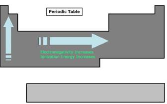
- Electronegativity in an element is a measure of the element's capability to attract another element's electrons. The higher degree of electronegativity an element has the more power it has to pull away electrons from a less electronegative element. There is an obvious trend in the periodic table for this particular property. Electronegativity generally increases from left to right and from bottom to top. As a result the elements around cesium have very low electronegativity and elements around fluorine have the highest.
- Ionization energy is the amount of energy required to remove an electron from an atom to form a cation. A cation is an ion or group of ions having a positive charge in electrolysis. This property also has a trend in the periodic table. It generally increases from left to right and from bottom to top.
The electronegativity and ionization energy values for the metals used in the lab are provided in the table below:
| Metal | Electronegativity (Pauling Scale) |
Ionization Energy (kJ/mole) |
| Magnesium | 1.31 | 738 |
| Nickel | 1.91 | 736 |
| Copper | 1.90 | 745 |
| Zinc | 1.65 | 904 |
| Aluminum | 1.61 | 577 |
The reaction that takes place in the lemon cell is called a redox reaction. This reaction can be simplified into two parts and they are called oxidation and reduction. Oxidation happens when there is an electron loss and reduction is when there is an electron gain. Oxidation and reduction can be shown in a half-reaction, which clearly shows the electron transfer. Take for example the redox reaction between magnesium and oxygen.
Failed to parse (MathML with SVG or PNG fallback (recommended for modern browsers and accessibility tools): Invalid response ("Math extension cannot connect to Restbase.") from server "https://wikimedia.org/api/rest_v1/":): {\displaystyle 2Mg(s) + O_2(g) \rightarrow 2MgO_2(s)}
When magnesium reacts with oxygen, magnesium loses electrons making it oxidized:
Failed to parse (MathML with SVG or PNG fallback (recommended for modern browsers and accessibility tools): Invalid response ("Math extension cannot connect to Restbase.") from server "https://wikimedia.org/api/rest_v1/":): {\displaystyle Mg(s) \rightarrow Mg^{2+}(s) + 2e^-}
At the same time, oxygen gains those electrons making oxygen reduced.
Hydrogen Fuel Cells
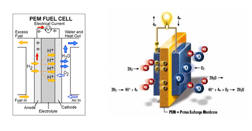
A fuel cell is a power storage device which stores chemical energy and converts it into electrical energy. The fuels used can range from hydrogen, methane to even gasoline. For the purpose of this lab we will be using hydrogen as a fuel; therefore we are using hydrogen fuel cells. The main components that make up the fuel cell are an electrolyte, an anode chamber, a cathode chamber, and bipolar plates. The electrolyte acts as a separator that keeps the reactions from interacting with each other, by separating the anode and cathode chambers. When the water molecules are broken down, the hydrogen is stored in the anode chamber and oxygen on the cathode chamber. The bipolar plates collect the current generated by the fuel cell when the reaction takes place. Refer to Figure 3 for the internal structure of a fuel cell. [4]
Generally the gas used by the fuel cell is already separated prior to the use with a fuel cell using various methods such as using an electrolyzer, a device that separates distilled water into hydrogen and oxygen. In some cases fuel cells can be used to initiate this reaction, they are called reversible fuel cells. When supplied with water the reversible fuel cell separates the distilled water into hydrogen and oxygen. The stored hydrogen and oxygen can then be supplied to the fuel cell to generate electrical energy. Hydrogen fuel cells can be used to power various utilities such as computers, cars, power plants and even whole cities. However due to the nature of producing and storing the gas required to generate large amounts of electrical energy fuel cells are generally very large. This becomes a problem when being used in vehicles.
Capacitors
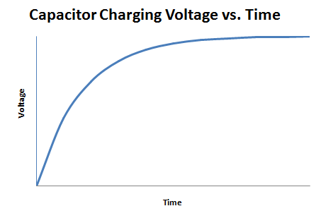
A capacitor is an electrical device used to store charge temporarily. Some capacitors can be used in place of a battery but they operate very differently from one. A capacitor is charged by a voltage source logarithmically, as shown in Figure 3.
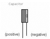
Because of their design, these capacitors are sensitive to the polarity of the voltage applied to them. The capacitors used in this lab must be connected with the proper polarity, or they will fail. Therefore, be sure to check the capacitor used to make sure you have the negative sign on the capacitor connected to the negative applied voltage. Failure to do this will cause the capacitors to fail.
The total energy a capacitor holds is given by the equation E = CV2 / 2. Note that the energy that the capacitor holds is proportional to the square of the voltage.
Types of Renewable Energy
Renewable energy are types of energy that can be harnessed from naturally replenished resources. Some examples of this includes sunlight, wind, and water. There are many benefits of using renewable energy such as clean energy sources, and they come from an abundant source that doesn’t become depleted. If we are able to efficiently utilize these renewable resources we can solve the problems with using non-renewable energy sources such as fossil fuels. [1]
Solar Power
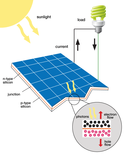
Sunlight, like any other type of electromagnetic radiation, contains energy. Typically when the sunlight hits an object, the energy that it contains is converted into heat. However, certain materials can convert the energy into electrical current, and in this form we can harness it and store it as energy.
In a crystal structure, the materials used for solar panels contain covalent bonds where electrons are shared by the atoms within the crystal. When the light is absorbed, electrons within the crystal become excited and move to a higher energy level. When this occurs the electron has more freedom of motion within the crystal. When the electrons move around the crystal structure an electrical current is generated, this in turn gives us electrical energy. The reaction that occurs when sunlight shines onto a solar panel is shown in Figure 5. [2]
Older solar panels consist of large crystalline structures made from silicon. When sunlight hits the silicon on the solar panel, the photons from the sunlight energize the electrons in the material. These energized electrons create a higher electrical potential in the material, which is measured as a voltage between that material and ground. The silicon solar panels convert a large amount of the sunlight into electrical energy but are not cost due to high manufacturing costs.[2]
The material Copper indium gallium (di)selenide (CIGS) is also used in the production of solar panels. Panels made from CIGS have a smaller crystalline structure and are less expensive than their silicon counterparts. CIGS panels are relatively flexible and can easily be shaped into flexible films. The use of CIGS to make solar panels is referred to as thin-film solar technology because of its flexible nature. CIGS panels are in fact not as good at converting absorbed light into electrical current compared to silicon. However, for mass production purposes, CIGS solar panels are the more cost effective approach to produce solar panels for frequent use. [2]
Wind Energy
Wind turbines are used to capture the wind’s energy and convert it into electrical energy. The structure of a wind turbine has a heavy influence on its functionality. The blades on wind turbines are slanted so that as the wind passes over the blades it creates an uneven pressure on each side causing them to spin. The spinning blades in turn drive a low speed shaft connected to a gearbox. The gearbox within the wind turbine converts the low speed rotation to a high speed rotation through a high speed shaft. The high speed shaft is connected to a brake and then into an electrical generator where mechanical energy is converted to electrical energy. [3]
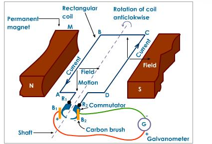
A very basic electrical generator is made up of permanent magnets on each side with a rectangular coil connected to a commutator, a rotary electrical switch. The two permanent magnets on each side create a magnetic field. As the rectangular coil spins mechanically, the magnetic field through the area of the coil changes creating an alternating current through the coil itself. The commutator switches the polarity of the coil just as the polarity of the alternating current changes creating a direct current. The current is then output from the wind turbine. [3]
Hydroelectric Power
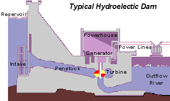
Water is constantly moved around in various states through the water cycle. Water evaporating from Earth’s surface condenses into clouds. The water in clouds over land will eventually precipitate in the form of rain effectively transporting water to a higher elevation and thus potential energy state. The energy is then release in the form of water flowing downstream. This movement provides opportunities to harness a seemingly infinite source of kinetic energy. In order to generate sufficient electricity from the motion of the water, it has to move fast enough and in large enough volumes to spin a turbine. The turbines used for hydroelectric energy operate in an almost identical manner to the turbines for used for wind power. The only differences occur in the physical construction of the turbine itself. In order to increase the volumes and motion of the water dams are created to store reservoirs of water.
Gravity causes the water held at the top of the dam to drop through the penstock (regulates water flow). At the end of the penstock is the turbine, which rotates thus creating the mechanical energy used to rotate the magnets in the generator.
Electrical Components
In electrical engineering different electrical components are represented by different symbols. Below in Figures 7a and 7b are examples of symbols for a cell and a battery.
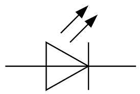
A diode is a device that allows current to pass through it in only one direction. This means that it has polarity, and will only allow current to pass from its positive side to its negative side. A Light Emitting Diode (LED) not only passes current, but also lights up when it's passing current. LEDs have a forward voltage and a reverse voltage. In the forward direction, the forward voltage and resistance are low and determined by the material used in the LED. The reverse voltage has a much higher resistance and a higher reverse voltage that prevents the flow of electrical current. The characteristic of the diode is to have low resistance to electrical flow in the forward direction and high residence in the reverse direction provides the ability to control the flow of electricity in one direction only.
There is a threshold voltage in the forward direction for the LED to emit light. Below the threshold voltage, there is no light. At and above the threshold voltage the LED emits light with intensity roughly linear with forward voltage. The symbol for the LED is shown in Figure 8.
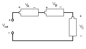
Different arrangements of electrical components allow engineers to design different devices. Components like resistors, inductors, and capacitors can be arranged in two different ways. In a series circuit, the element's conductors are connected end to end. The current in a series circuit remains the same in all the electrical elements. In a series circuit, as shown in Figure 9, the sum of the voltages across each element is equal to the voltage of the power source (Vout = VA + VB + VC).
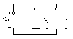
In a parallel circuit, as shown in Figure 10, the element's conductors are connected at opposing ends. The current that is supplied by the voltage source equals the current that flows though elements D and E. The voltage across the elements that are parallel is the same (Vout = VD = VE).
The motor provided is a 9V motor that will operate with voltages lower than 9V with reduced torque and speed. A motor with no load draws 9mA; a stalled motor draws well over 350mA. By increasing the voltage provided to the motor you can increase the motor speed. By increasing current you increase the torque.
Design Considerations
- Which source yields the most voltage per unit cost?
- Which type of energy storage is most effective?
- Which circuit configuration will provide the most desirable voltage across the load? Parallel or series?
- Which aspects of the competition formula are most advantageous?
Materials and Equipment
Materials with Price List
- 2oz Lemon Juice (with cup): $0.50
- Cu, Zn: $0.75/strip
- Horizon wind-turbine: $7.50 each
- Water turbine: $5.00 each
- Solar battery panels: $10.00 each
- Horizon hydrogen fuel cell: $4.00 each
- 1 Farad 5.5V capacitor: $3.00 each
- Alligator cable sets: $0.50/pair
- Standard Lego car chassis plus Lego parts kit: $0, limit one per group
- Lego to alligator cable clip connector: $0.10 each
- Duct Tape: $0.10/feet
Equipment Used
- Horizon Wind-Turbine
- Sunforce 50013 1-Watt Solar Battery Charger
- Adjustable Table fan
- Heat Lamp
- DMM (Digital Multi-meter)
- Music Voltmeter
- 2V DC Motor
- Horizon Hydrogen Fuel cell
- 1 Farad 5.5V Capacitor
- Lemon Juice
- Metal Strips
- Zinc, Copper
- 3 Alligator cable sets
- Standard Lego Car Chassis plus Lego parts kit
- Lego to Alligator Cable Clip Connector
- Scissors
- Tape
Warning Magnesium is a highly reactive metal. Use carefully and only as described in these instructions.
Procedure
Every group will be designated to test a pair of power storage devices and power sources.
Part 1: Testing the Power Storage Devices
Electrolytic/Citrus Cell
In this part of the experiment every team will receive a set of metals to test and compare the different voltage outputs of the combinations.
- Obtain two different samples of metals from your TA as well as one cup of lemon juice.
- Before inserting metal strips into the cup of lemon juice, clean the metal strips using the emery paper provided by the TA. Scrub the emery paper in one direction, then scrub perpendicular to the first direction. Once cleaned, insert the metals into the cup of lemon juice. Note: Magnesium reacts very fast, so if this is one of the metals given be sure to insert both strips at the same time and take readings immediately.
- Keep the metals on opposite sides of the cup to prevent them from touching.
- Connect one end of the first alligator cable set to one of the metal pieces and one end of the second alligator cable set to the other metal. These will be the electrodes of the cell.
- Connect the other ends of the alligator cable sets to the positive and negative ends of the digital multi-meter and measure the voltage. Record the value in units of volts. Note: If it is negative then the polarity is switched; switch the alligator clips to connect to the opposite sides of the DMM.
- The metal strip attached to the positive end of the digital multi-meter (red wire) is the anode (+) and the other (black wire) is the cathode (-).
- Record the values and present them to your TA. The TA will generate a spreadsheet with the voltage produced by each metal combination for all teams.
- Remove the electrodes to stop the chemical reaction. Wipe them clean with a paper towel. Discard the paper towel in the trash can.
Warning Magnesium left in lemon juice dissolves; remove from the cup immediately after this part of the experiment.
Hydrogen Fuel Cell
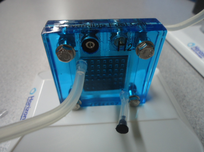
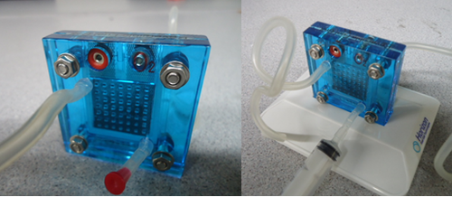
- Place the 2x4cm (small) length pieces of rubber tube into the bottom right pin on the hydrogen fuel cell (on both sides) and insert a cap (red for oxygen and black for hydrogen) into the other end of the tube.
- Insert the two longer tubes into the top left pin of the hydrogen fuel cell.
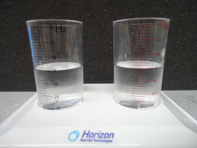
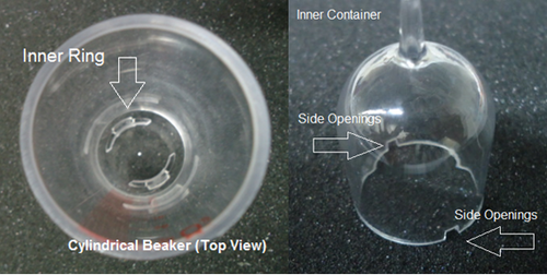
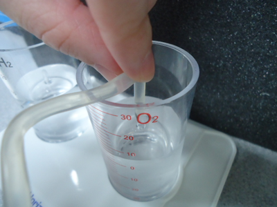
- Take the two cylindrical beakers and place them on top of the stand provided locking it in place, then fill the two beakers with distilled water until the water level reaches zero.
- Place the two inner containers into the cylindrical beakers (make sure the side openings on the inner container is not blocked by the inner ring on the beakers), the distilled water from the beaker will fill out the inner container at this point.
- Connect the two longer tubes to the inner container on each of the beakers corresponding to oxygen and hydrogen on the fuel cell. (Make sure there is no air in the inner containers.)
- On the oxygen side of the fuel cell connect the syringe to the uncapped tube (first remove the red cap on the smaller tube). Fill the reversible fuel cell with distilled water using the syringe (by pulling out the air, not pushing in water) until all the air is removed from the long tube. Afterwards place the red cap on the smaller tube
- IMPORTANT: Make sure the connections of the wires to the fuel cell match (red to red, black to black) otherwise it may lead to failure of this part of the experiment and damage to the fuel cell. If this problem occurs the students will have to take full responsibility for replacing the parts.
- Hint: Place the longer tube above the oxygen beaker to hold the water coming out of the longer tube.
- Connect the 3V power supply to the positive and negative inputs on the fuel cell and turn on the power supply.
- Charge until H2 inner container is filled with gas. The O2 should be half because we're converting H2O and the stoichiometric coefficients demand that balance.
- Discharge the charged fuel cell by connecting it to the music voltmeter provided.
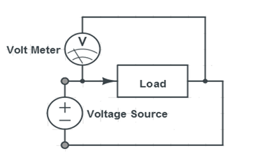
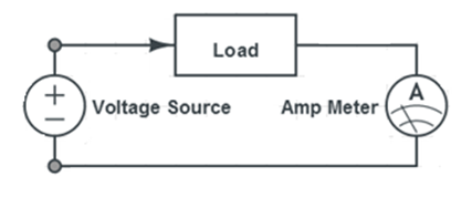
- Measure the voltage and current across the music voltmeter using the digital multimeter provided. The connections for measuring voltage and current across the music voltmeter are shown in Figures X & Y:
- Note: Be careful to not wire the multimeter in the voltage-reading configuration when reading current; accidentally doing this will cause the multimeter to blow its fuse and become inoperable.
- Calculate and record the power produced by the hydrogen fuel cell.
Charging a Capacitor
- Connect an alligator clip to each of the cables coming out of the 3V power supply. (red is positive and black is negative)
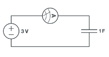
- Connect to the one of unconnected alligator clips the ammeter (multimeter setting measuring current)
- Connect the rest of the unconnected cables (one from ammeter and one alligator clip) connect to pins of the capacitor with correspond polarity. (refer to Figure 10)
- Charge until the current is zero.
- Discharge the charged capacitor by connecting it to the music voltmeter provided.
Part 2: Testing the Power Sources
Each team will analyze one type of renewable power source, determined by the TA. Both voltage and current must be measured and recorded, and power must be calculated.
Wind turbine
- Connect the wind turbine to the music voltmeter using the alligator clips provided. Measure the voltage and current across the music voltmeter using the digital multimeter provided. The connections for measuring voltage and current across the music voltmeter are shown in Figures 9 & 10.
- Adjust the position of the turbine to find the maximum voltage and current that can be generated.
- Calculate and record the power generated by the turbine and give information to TA.
Solar Panel
- Connect the solar panel to the music voltmeter using the alligator clips provided. Place the solar panel near the heat lamp and measure the voltage and current across the music voltmeter using the digital multimeter provided.
- Adjust the position of the solar panel to find the maximum voltage and current that can be generated.
- Calculate and record the power generated by the solar panel and give information to the TA.
- Caution! The heat lamps and solar panels may become extremely hot when used for a long duration of time. Do not touch them immediately after use and turn them off when not in use.
Water Turbine
- Connect the leads of the hydroelectric turbine to the music voltmeter using the alligator clips provided.
- Ask a TA to open the spigot on the bucket at the top of the workbench.
- Calculate and record the power generated by the solar panel and give information to the TA.
Hydroelectric Turbine
- Connect the red wire of the water wheel to the positive (red) end of the multimeter and the black wire to the negative (black) end of the multimeter. Set the multimeter to measure voltage.
- Notify the TA once the connections have been set up. The TA will then take you to the AUV room's sink to measure the voltage and (electrical) current produced by the water coming from the sink. Be very careful to keep water off of the multimeters.
- Calculate and record the power generated by the water wheel and give information to the TA.
Part 3: Renewable Car Competition
- Assess your materials and consider the data established from Part 1 and Part 2. Choose materials for your car design, keeping in mind the Competition Ratio. Make sure you make preliminary sketches during this process. (You may choose different combinations of power sources and power storage devices for your design)
- Your design must be able to hold the power storage devices on top of it during the trials (you may modify your design to fit the power storage devices as you deem fit). Prepare a price-list for your renewable energy powered vehicle based on the setups and materials you have chosen. Have your TA sign the sketches and the price-list.
- Your TA will provide the materials needed for your design. If you decide to modify your design during the construction of your car, note the changes and describe the reasons for them. If the modifications required more materials to be used, make sure you update your price list and your TA approves it. (Note: You may modify your design between trials)
Before entering the competition, test if both your motor and cable are working.
Competition
The renewable energy vehicle must be able to carry the power storage device you choose to use on it (e.g. fuel cell, capacitor). You may only power your capacitor and fuel cell using the power sources provided, violations to these rules will result in a failing grade for the lab report for this lab.
When requested by the TA, the student will position the renewable energy car and complete the necessary connections before the trial begins.
The competition will be won by the team that has the highest competition ratio:
Failed to parse (MathML with SVG or PNG fallback (recommended for modern browsers and accessibility tools): Invalid response ("Math extension cannot connect to Restbase.") from server "https://wikimedia.org/api/rest_v1/":): {\displaystyle CR = \frac{distance\left[\text{ft}\right]}{1\left[\text{s}\right] + time\left[\text{s}\right]} \times \frac{100}{Cost\left[$\right]} + distance\left[\text{ft}\right]\,}
The TA will record the test data after five minutes or when the car stops moving, whichever occurs first. The TA will then calculate the competition ratio. The tabulation for the whole class will be provided.
Assignment
Individual Lab Report
Follow the lab report guidelines laid out in the page called Specifications for Writing Your Lab Reports in the Technical Communication section of this manual. As you write, the following discussion points should be addressed in the appropriate section of your lab report:
- Describe the rules of the competition in your introduction. What consequences did the rules have for your design decisions? Use the appropriate equations in your answer.
- Describe an electrolytic cell in your introduction. What consequences did the electrode voltages have for your design decisions?
- Explain how solar panels and wind turbines work.
- Explain the concepts of the hydrogen fuel cell and capacitors.
- Discuss the advantages and disadvantages of the solar panel and wind-turbine..
- Discuss the advantages and disadvantages of hydrogen fuel cell compared to other storage devices (e.g. capacitors or batteries)
- Describe your renewable energy vehicle design and explain the choices you made in your design.
- Discuss minimal design. Did you use all the materials you purchased? Describe the importance of minimal design and explain how you employed it in your design. (how did you minimize your cost)
- Describe how your design succeeded or failed. What choices could you have made to improve your final standing in the competition?
- Discuss how you would improve the competition ratio, how was your design compared to the other group’s designs.
- Describe the power source chosen for the design.
- Include spreadsheet with every team's results. Describe the results and talk about other designs in the class.
Remember: Lab notes must be taken. Experimental details are easily forgotten unless written down. EG1004 Lab Notes Paper can be downloaded and printed from the EG1004 Website. Use the lab notes to write the Procedure section of the lab report. At the end of each lab, a TA will scan the lab notes and upload them to the Lab Documents section of the EG1004 Website. One point of extra credit is awarded if the lab notes are attached at the end of the lab report. Keeping careful notes is an essential component of all scientific practice.
Team PowerPoint Presentation
Follow the presentation guidelines laid out in the EG1003 Lab Presentation Format section of this manual. When you are preparing your presentation, consider the following points:
- Since one term in the competition ratio is cost, present the cost of your vehicle. Use the page How to Show Cost Data in Presentations for instructions on how to do this.
- How would you improve your renewable energy powered car?
References
[1] NextEra Energy Resources, LLC., . "Benefits of Renewable Energy." NextEra Energy Resources. NextEra Energy Resources, 2012. Web. 24 Jul 2012. <http://www.nexteraenergyresources.com/content/environment/benefits.shtml>.
[2] Locke, S.. "How does solar power work." Scientific american. Scientific American, 2008. Web. 24 Jul 2012. <http://www.scientificamerican.com/article.cfm?id=how-does-solar-power-work>.
[3] Layton, J.. "How Wind Power Works." How stuff works. Discovery, 2011. Web. 24 Jul 2012. <http://science.howstuffworks.com/environmental/green-science/wind-power.htm>.
[4] Reg Tyler, . "Types of Fuel Cells." Energy efficeny and renewable energy. U.S. Department of Energy, 2011. Web. 24 Jul 2012. <http://www1.eere.energy.gov/hydrogenandfuelcells/fuelcells/fc_types.html>.
[5] Perlman, Howard.. "Hydroelectric power: How it works." U.S. Geological Survey, 2016. Web 4 Jan 2018. <https://water.usgs.gov/edu/hyhowworks.html>.
