Difference between revisions of "RAD Workshop"
| (37 intermediate revisions by 4 users not shown) | |||
| Line 1: | Line 1: | ||
= Objective = | = Objective = | ||
The objective of this workshop is to explore the capabilities of a Raspberry Pi, utilize computer vision to detect objects by color | The objective of this workshop is to explore the capabilities of a Raspberry Pi, utilize computer vision to detect objects by color and integrate servo motor control with the color detection output. | ||
= Overview = | = Overview = | ||
| Line 23: | Line 23: | ||
=== Syntax === | === Syntax === | ||
Unlike other programming languages, Python does not require a closing mark on lines of code. Lines of code are closed off by continuing onto the next line. | Unlike many other programming languages, Python does not require a closing mark on lines of code. Lines of code are closed off by continuing onto the next line. | ||
In Figure 3, the program will print <b>“Hello World”</b>, make a variable, <b>x</b> | In Figure 3, the program will print <b>“Hello World”</b>, make a variable, <b>x</b> with an assigned value of 3, make a variable, <b>y</b> with an assigned value of 2, add the two variables together, store the sum in a variable named <b>result</b>, and print the result. | ||
[[Image:Lab_PythonSyntax.jpg|500px|thumb|center|Figure 3: Python Syntax]] | [[Image:Lab_PythonSyntax.jpg|500px|thumb|center|Figure 3: Python Syntax]] | ||
=== Loops === | === Loops and Conditionals === | ||
For | For loops and conditionals made (while/for loops, if/elif/else), the lines following the initial declaration of the loop/conditional must be indented (Figure 4). The lack of indentation will cause a syntax error. In Figure 4, the program will determine if <b>5</b> is greater than <b>2</b>, and if true, print <b>“Five is greater than two!”</b>. | ||
[[Image:Lab_PythonIfStatement.jpg|500px|thumb|center|Figure 4: If Statement]] | [[Image:Lab_PythonIfStatement.jpg|500px|thumb|center|Figure 4: If Statement]] | ||
| Line 54: | Line 54: | ||
== Computer Vision (CV) == | == Computer Vision (CV) == | ||
Computer vision is an area of artificial intelligence (AI) that allows computers and systems to measure data from visual inputs and produce outputs based on that data. The OpenCV library is an extensive open source library used for computer vision. OpenCV contains interfaces for multiple programming languages. | Computer vision is an area of artificial intelligence (AI) that allows computers and systems to measure data from visual inputs and produce outputs based on that data. The OpenCV library is an extensive open-source library used for computer vision. OpenCV contains interfaces for multiple programming languages. | ||
OpenCV allows image/video processing and display, object detection, geometry-based monocular or stereo computer vision, computational photography, machine learning and clustering, and CUDA acceleration. With this functionality, many applications are possible including facial recognition, street view image stitching, and driverless car navigation. | OpenCV allows image/video processing and display, object detection, geometry-based monocular or stereo computer vision, computational photography, machine learning and clustering, and CUDA acceleration. With this functionality, many applications are possible including facial recognition, street view image stitching, and driverless car navigation. | ||
In OpenCV, color images are represented as three-dimensional arrays. An image consists of rows of pixels, and each pixel is represented by an array of values representing its color in BGR (Blue, Green, Red) format. The array can be transcribed into the color’s specific hue saturation value (HSV). The HSV model describes colors similar to how the human eye tends to perceive color. This format is more suitable for color detection purposes. | In OpenCV, color images are represented as three-dimensional arrays. An image consists of rows of pixels, and each pixel is represented by an array of values representing its color in BGR (Blue, Green, Red) format (Figure 9). | ||
[[Image:BRG_Color_Format.png|500px|thumb|center| Figure 9: BGR Color Format Courtesy of Mastering OpenCV 4 with Python]] | |||
The array can be transcribed into the color’s specific hue saturation value (HSV). The HSV model describes colors similar to how the human eye tends to perceive color. This format is more suitable for color detection purposes (Figure 10). | |||
[[Image:HSV_Color_Space.png|500px|thumb|center| Figure 10: HSV Color Space in OpenCV Courtesy of Python Image Processing Cookbook]] | |||
=== cv2.cvtColor() === | === cv2.cvtColor() === | ||
| Line 65: | Line 72: | ||
=== cv2.inRange() === | === cv2.inRange() === | ||
<b>cv2.inRange(frame, lower bound, upper bound)</b> is a method used to identify pixels in the frame that fall within the range of values defined by the lower and upper boundaries. This command outputs a binary mask where white pixels represent areas that fall within the range, and black pixels represent areas that do not fall within the range. The right panel in Figure | <b>cv2.inRange(frame, lower bound, upper bound)</b> is a method used to identify pixels in the frame that fall within the range of values defined by the lower and upper boundaries. This command outputs a binary mask where white pixels represent areas that fall within the range, and black pixels represent areas that do not fall within the range. The right panel in Figure 11 shows the output for the <b>cv2.inRange()</b> method using the command <b>orange_mask = cv2.inRange(nemo,lower,upper)</b>. The bright orange pixels fall within the range specified and have a corresponding white value in the output. | ||
[[Image:Lab_PythonInRange.jpg|500px|thumb|center| Figure | [[Image:Lab_PythonInRange.jpg|500px|thumb|center| Figure 11: cv2.inRange() Method Courtesy of Real Python]] | ||
=== cv2.bitwise_and() === | === cv2.bitwise_and() === | ||
<b>cv2.bitwise_and(frame, frame, mask = mask)</b> is a bitwise AND operation that delegates in making the frame only retain what is determined by the set mask. Only pixels in the frame with a corresponding white value in the mask would be preserved. The rightmost panel in Figure | <b>cv2.bitwise_and(frame, frame, mask = mask)</b> is a bitwise AND operation that delegates in making the frame only retain what is determined by the set mask. Only pixels in the frame with a corresponding white value in the mask would be preserved. The rightmost panel in Figure 12 shows the output of the command <b>cv2.bitwise_and(nemo, nemo, mask=orange_mask)</b>. | ||
[[Image:Lab_PythonAND.jpg|500px|thumb|center| Figure | [[Image:Lab_PythonAND.jpg|500px|thumb|center| Figure 12: Input, Mask, and Bitwise-And Output Courtesy of Real Python]] | ||
=== cv2.bitwise_or() === | === cv2.bitwise_or() === | ||
| Line 81: | Line 88: | ||
== NumPy == | == NumPy == | ||
Numerical Python (NumPy) is a Python library used primarily for working with arrays. The library also contains functions for mathematical purposes, such as linear algebra, | Numerical Python (NumPy) is a Python library used primarily for working with arrays. The library also contains functions for mathematical purposes, such as linear algebra, Fourier transformation, and matrices. In this lab, the NumPy command used is <b>np.array</b>. | ||
=== np.array() === | === np.array() === | ||
<b>np.array()</b> creates an array object of the class N-dimensional NumPy array | <b>np.array()</b> creates an array object of the class N-dimensional NumPy array or <b>numpy.ndarray</b>. A list, tuple, or number can be entered in the parentheses to turn the data type into an array. | ||
== | == USB Camera == | ||
The USB Camera Module is a camera that can be used to capture high-resolution and high-definition images and video. The module’s library features commands to use the camera within code and modify how the camera outputs the frame rate, resolution, and timing of the image or video it is capturing. The camera module’s coding library (picamera) is automatically installed onto a Raspberry Pi once the camera is enabled and the Raspberry Pi is rebooted. | |||
=== camera. | === camera.set (cv2.CAP_PROP_FRAME_WIDTH, width) or camera.set(cv2.CAP_PROP_FRAME_HEIGHT, height) === | ||
'''camera.set()''' sets a specific resolution (width/height) for the frame in teh video stream. The maximum resolution for still photos is 2592 x 1944 pixels and 1920 x 1080 pixels for video recording. The minimum resolution is 64 x 64 pixels. | |||
=== camera. | === camera.read() === | ||
'''camera.read()''' reads the current frame from the camera. | |||
=== camera.cv2.VideoCapture() === | |||
'''camera = cv2.VideoCapture(0)''' declares camera as an object for all function calls later and enables the camera module to capture an image in video format. | |||
== Raspberry Pi Setup == | == Raspberry Pi Setup == | ||
| Line 112: | Line 111: | ||
=== Continuous vs. Positional Servo Motor === | === Continuous vs. Positional Servo Motor === | ||
A servo motor is a compact actuation device with high power output and energy efficiency. There are two kinds of servo motors used for common applications - continuous rotation and positional rotation servos. A continuous servo motor has a shaft that spins continuously allowing definite control over its speed and direction. A positional servo motor can only turn over a range of 180 degrees (90 degrees in each direction), allowing precise control over its position (Figure | A servo motor is a compact actuation device with high power output and energy efficiency. There are two kinds of servo motors used for common applications - continuous rotation and positional rotation servos. A continuous servo motor has a shaft that spins continuously allowing definite control over its speed and direction. A positional servo motor can only turn over a range of 180 degrees (90 degrees in each direction), allowing precise control over its position (Figure 13). | ||
[[Image:Lab_Servo_Comp.png|500px|thumb|center| Figure | [[Image:Lab_Servo_Comp.png|500px|thumb|center| Figure 13: Servo Comparison Diagram]] | ||
== Programming Servo Motors (Raspberry Pi) == | == Programming Servo Motors (Raspberry Pi) == | ||
| Line 142: | Line 141: | ||
= Materials and Equipment = | = Materials and Equipment = | ||
* Raspberry Pi with SD card | * Raspberry Pi with SD card | ||
* | * USB Camera | ||
* Monitor with micro HDMI to HDMI cable | * Monitor with micro HDMI to HDMI cable | ||
* USB keyboard | * USB keyboard | ||
| Line 162: | Line 161: | ||
Raspberry Pi will boot up and the monitor will display the desktop. This concludes the Pi setup. | Raspberry Pi will boot up and the monitor will display the desktop. This concludes the Pi setup. | ||
== Setting up the Camera | == Setting up the USB Camera == | ||
The following steps outline the procedure for connecting | The following steps outline the procedure for connecting the camera module. | ||
# Locate the <b> | # Locate the <b>USB</b> port and insert the USB Camera, as shown in Figure 14.Ensure the Raspberry Pi is powered off. | ||
[[Image:USB_Port.png|500px|thumb|center| Figure 14: Servo Motor Connection to Raspberry Pi - Courtesy of Raspberry Pi Projects]] | |||
# | # Turn on the Raspberry Pi, and open the terminal on the top left corner of the screen. | ||
#: | # Enter the following: '''"sudo apt-get install fswebcam"''' to install the webcam library. | ||
# | # Enter the following: '''"lsusb"''' and check that USB is reading the camera. | ||
# Enter the following: '''"fswebcam testpic.jpg"''' to take a test picture. | |||
# | # Open the file explorer on the top left, and verify that the test picture was successful. | ||
# | |||
== Part 1: | == Part 1: Wiring the Servo Motor == | ||
# Wire the servo motor according to the following diagram. Make sure to wire the servo pin to GPIO 17 on the Raspberry Pi, as shown in Figure 15. | |||
[[Image:Lab_Servo_Motor_Connection.png|500px|thumb|center| Figure 15: Servo Motor Connection to Raspberry Pi - Courtesy of Raspberry Pi Projects]] | |||
== Part 2: Color Detection using USB Camera and Python-OpenCV == | |||
== Part 2 | |||
In this part, a Python script that isolates red and green colors from a live video captured by the camera module will be developed and this output will be used to create a prototype of a traffic light detection system. | In this part, a Python script that isolates red and green colors from a live video captured by the camera module will be developed and this output will be used to create a prototype of a traffic light detection system. | ||
# Download the [[Media: | # Download the [[Media:Lab3A_RAD_StudentVersion.zip| Python script]] for color detection using OpenCV. Open the camera module with the Thonny Python Editor installed on the Raspberry Pi. | ||
# There are missing components in the program. Complete the code following the instructions outlined in the next steps. | # There are missing components in the program. Complete the code following the instructions outlined in the next steps. | ||
# The code is divided into four sections. Figure | # The code is divided into four sections. Figure 16 shows the workflow for this lab. | ||
## Section 1 includes commands for importing all necessary packages and setting up the GPIO pins on the Pi. | ## Section 1 includes commands for importing all necessary packages and setting up the GPIO pins on the Pi. | ||
## Section 2 sets up the camera module so it captures a continuous video. | ## Section 2 sets up the camera module so it captures a continuous video. | ||
## Section 3 contains code for color detection and isolation for red and green colors. | ## Section 3 contains code for color detection and isolation for red and green colors. | ||
## Section 4 integrates the servo motor with the color detection output such that the servo rotates clockwise when red is detected, counterclockwise when green is detected, and stops rotating when neither red nor green is detected. | ## Section 4 integrates the servo motor with the color detection output such that the servo rotates clockwise when red is detected, counterclockwise when green is detected, and stops rotating when neither red nor green is detected. | ||
## | ##: [[Image:Lab_RaspberryPiFlowChart.png|600px|thumb|center| Figure 16: Lab Workflow]] | ||
# Type the code in Figure | # Section 1 of the code consists of packages that are to be included. Type the code in Figure 17 to import the required packages into the Python module. (Note: code is case sensitive, copy the code exactly as it is shown below) | ||
# | #: [[Image:Lab_PythonPackageImport.png|400px|thumb|center| Figure 17: Importing Python Packages]] | ||
## OpenCV represents images as NumPy arrays. Lines 3-5 import OpenCV, NumPy, and | ## OpenCV represents images as NumPy arrays. Lines 3-5 import OpenCV, NumPy, and Picamera2 libraries. The images obtained from the camera module must be in an array format so Line 6 is included.Line 7 imports the Raspberry Pi GPIO library. | ||
## Assign a variable for the servo pin. Based on the wiring diagram, the servo should be wired to pin 17 on the Raspberry Pi. | ## Assign a variable for the servo pin. Based on the wiring diagram, the servo should be wired to pin 17 on the Raspberry Pi. | ||
##Set GPIO mode to GPIO.BCM | ##Set GPIO mode to GPIO.BCM | ||
## Set the mode for the servo pin as output. This completes section 1 of the code. | ## Set the mode for the servo pin as output. This completes section 1 of the code. | ||
# Section 2 of the code sets up the camera module. The <b>while(True):</b> condition creates an infinite loop so that the code re-runs automatically to perform color detection on a set of objects. In the body of the <b>while loop</b>, type out a command for each of the following tasks using the background information of the camera module commands as reference. | # Section 2 of the code sets up the camera module. The <b>while(True):</b> condition creates an infinite loop so that the code re-runs automatically to perform color detection on a set of objects. In the body of the <b>while loop</b>, type out a command for each of the following tasks using the background information of the camera module commands as reference. | ||
## Get the code approved by a TA and move to the next step. | |||
# Section 3 is image processing. The next step is to capture a continuous video array with the camera. This is achieved by using the <b>camera.read()</b> command as shown on <b>Line 23</b> in the figure below. <b>Line 27</b> converts every frame captured by the camera module from a BGR color format to an HSV format, ready to be manipulated with OpenCV to perform color detection. | |||
#:[[Image:Lab_RaspberryPiVideo.jpg|500px|thumb|center| Figure 18: Capturing Continuous Video and Converting BGR to HSV]] | |||
## Get | # Next is to perform color detection for red and green colors. Since it is easier to identify these colors with their HSV, each frame is converted from the default BGR format to the HSV format. Line 26 in Figure 19 performed this task using the <b> cv2.cvtColor</b> method. The newly created HSV frame (stored as variable hsvFrame) will now be used for color detection. | ||
# | # The segment of code in Figure 19 will isolate red from the video. <b>Lines 29-30</b> define the lower and upper boundaries of the range of HSV values within which the color would be classified as red. These values might have to be adjusted based on lighting and exposure conditions. | ||
# | #: [[Image:Lab_RaspberryPiColor.png|500px|thumb|center| Figure 19: Color Detection for Red]] | ||
# | ## <b>Line 31</b>, identifies all the pixels in the video that fall within the specified range by defining a variable <b>red_mask</b>, and using the <b>cv2.InRange</b> method using <b>red_lower</b> and <b>red_upper</b> as boundaries. This line outputs a binary mask where white pixels represent areas that fall within the range, and black pixels represent areas that do not. | ||
# The segment of code in Figure | ## <b>Line 32</b> applies the mask over the video to isolate red using the <b>cv2.bitwise_and</b> method taking <b>frame</b> as the input, and outputting frame using <b>red_mask</b> as the mask. This line outputs the frame so that only pixels that have a corresponding white value in the mask are shown. | ||
# | # Insert code that will be used to isolate green from the video. Use the lower boundary values [20,40,60] and upper boundary values [102, 255, 255] to define the range. | ||
## <b>Line | # To isolate both red and green from the video at once, combine <b>result_red</b> and <b>result_green</b>. Think about how this could be achieved and type out the correct command in <b>Line 40</b> (Figure 20). Which bitwise operation should be used to show pixels where either red or green are present? | ||
## <b>Line | #: [[Image:Lab_RaspberryPiResults.jpg|500px|thumb|center| Figure 20: Result Statements]] | ||
# Insert code | # To display the final result (<b>Line 42</b>), type a line of code that creates a new window named "Red and Green Detection in Real-Time" which will display the final output. Use the <b>cv2.imshow</b> method. | ||
# To isolate both red and green from the video at once, combine <b>result_red</b> and <b>result_green</b>. Think about how this could be achieved and type out the correct command in <b>Line | |||
# | |||
# To display the final result (<b>Line | |||
## This concludes Section 3 of the program. Get the code approved by a TA and move to Section 4. | ## This concludes Section 3 of the program. Get the code approved by a TA and move to Section 4. | ||
# <b>Lines | # <b>Lines 46-63</b> represent the final section of the program. The objective of this section is to integrate the color detection output with servo rotation. The servo would rotate clockwise when a red object is detected, counterclockwise when a green object is detected, and stop rotation when neither red nor green is detected. | ||
# | #: [[Image:Lab_TrafficLights.png|500px|thumb|center| Figure 21: Traffic Light Detection System]] | ||
##<b> | ##<b>Line 46</b> dictates that every time the key ‘q’ is pressed, the camera closes and stops capturing new frames. The final frame is checked for the presence of red and green using <b>if</b> statements <b>(lines 47-59)</b>. | ||
##The following conditions are implemented for detecting red color <b>( | ##The following conditions are implemented for detecting red color in the video <b>(lines 47-48)</b> the frame should have more red pixels than green, and the number of red pixels should be at least 25% of the total number of pixels. The <b>cv2.countNonZero</b> method is used on <b>red_mask</b> to obtain the number of red pixels. | ||
##On <b>line 50</b>, insert a command to start servo rotation with a 5% duty cycle. This corresponds to clockwise rotation. | ##On <b>line 50</b>, insert a command to start servo rotation with a 5% duty cycle (using the commands discussed in earlier sections). This corresponds to clockwise rotation. | ||
##Insert the following conditions for detecting green color <b>(line 52) | ##Insert the following conditions for detecting green color <b>(line 52)</b> the frame should have more green pixels than red, and the number of green pixels should be at least 25% of the total number of pixels. | ||
##On <b>line | ##On <b>line 55</b>, insert a command to start servo rotation with a 55% duty cycle. This corresponds to counterclockwise rotation. | ||
##On <b>line | ##On <b>line 59</b>, insert a command to stop servo rotation. | ||
# Run the Python script and place the red and green objects provided by the TAs in front of the camera module. Observe how the specified colors are isolated from the video output. Press the q key on the keyboard to pause the video at a specific frame and observe the output print statements. Figure | # Run the Python script and place the red and green objects provided by the TAs in front of the camera module. Observe how the specified colors are isolated from the video output. Press the q key on the keyboard to pause the video at a specific frame and observe the output print statements. Figure 22 displays what the final output would look like when a red object is held up to the camera module. | ||
# | #: [[Image:Lab_TrafficLightsFinal.jpg|300px|thumb|center| Figure 22: Final Output]] | ||
This concludes the procedure for this workshop. | This concludes the procedure for this workshop. | ||
= Assignment = | = Assignment = | ||
== Individual Lab Report == | == Individual Lab Report == | ||
There is | There is '''no''' lab report for Lab 3. | ||
==Team PowerPoint Presentation == | |||
== Team PowerPoint Presentation == | There is '''no''' team presentation for Lab 3. | ||
There is | |||
= References = | = References = | ||
| Line 290: | Line 273: | ||
* PiCamera with [array] submodule | * PiCamera with [array] submodule | ||
# Open a terminal window by clicking the black monitor icon on the taskbar (Figure | # Open a terminal window by clicking the black monitor icon on the taskbar (Figure 25). | ||
#; [[Image:Lab_RaspberryPiTaskbar.jpg|500px|thumb|center| Figure | #; [[Image:Lab_RaspberryPiTaskbar.jpg|500px|thumb|center| Figure 25: Taskbar]] | ||
# Before installing the required packages, install PIP, update the system, and install Python 3 using the commands <b>PIP for python3 - sudo apt-get install python 3-pip, sudo apt-get update && sudo apt-get upgrade, and sudo apt-get install python3</b>. | # Before installing the required packages, install PIP, update the system, and install Python 3 using the commands <b>PIP for python3 - sudo apt-get install python 3-pip, sudo apt-get update && sudo apt-get upgrade, and sudo apt-get install python3</b>. | ||
# To install OpenCV, NumPy, and PiCamera packages, type out the following commands <b>sudo pip3 install opencv-python, sudo pip3 install numpy, and sudo pip3 install picamera[array]</b>. | # To install OpenCV, NumPy, and PiCamera packages, type out the following commands <b>sudo pip3 install opencv-python, sudo pip3 install numpy, and sudo pip3 install picamera[array]</b>. | ||
# Optionally, to utilize the GPIO pins on the Raspberry Pi, install the GPIO library using the following command <b>sudo pip-3.2 install RPi.GPIO</b>. | # Optionally, to utilize the GPIO pins on the Raspberry Pi, install the GPIO library using the following command <b>sudo pip-3.2 install RPi.GPIO</b>. | ||
Latest revision as of 21:21, 26 September 2024
Objective
The objective of this workshop is to explore the capabilities of a Raspberry Pi, utilize computer vision to detect objects by color and integrate servo motor control with the color detection output.
Overview
Raspberry Pi
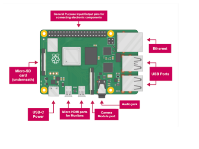
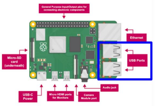
A Raspberry Pi is a single-board, small computer that is used for electronic projects or as a component in larger systems (Figure 1). The default operating system is Raspberry Pi OS, a Debian-based operating system. A Raspberry Pi can also operate using Linux distros or Android. Internally, a Raspberry Pi has a central processing unit (CPU), graphics processing unit (GPU), and random-access memory (RAM) and can perform more advanced tasks, such as character recognition, object recognition, and machine learning, compared to Arduino.
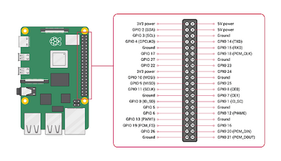
The base hardware of a Raspberry Pi 4 features USB 2.0/3.0 ports for peripherals, a wireless and ethernet port, Bluetooth, USB-C power, general-purpose input/output (GPIO) pins (Figure 2), an audio jack, two micro HDMI ports, and a camera module port.
A Raspberry Pi has 28 GPIO pins, two 5V pins, two 3.3V pins, and eight ground pins. The 28 GPIO pins are analogous to Arduino digital/analog I/O pins and allow connections to sensors and additional components, such as an Arduino board.
The data storage for a Raspberry Pi uses an SD card. Many programming languages can be used on the Raspberry Pi, including Python, Scratch, Java, and C/C++. The Python programming interface is the default for a Raspberry Pi. Thonny IDE is the environment for Raspberry Pi when using Python.
To further the capabilities of a Raspberry Pi, additional modules, such as a camera module, microcontrollers, and programming libraries, such as the Open Source Computer Vision Library (OpenCV), can be implemented.
Python
Python is a text-based programming language typically used for web development, software development, mathematics, and system scripting. Python is functional across several platforms and has syntax similar to the English language, which minimizes the amount of code needed to perform certain tasks compared to other languages.
Syntax
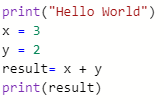
Unlike many other programming languages, Python does not require a closing mark on lines of code. Lines of code are closed off by continuing onto the next line.
In Figure 3, the program will print “Hello World”, make a variable, x with an assigned value of 3, make a variable, y with an assigned value of 2, add the two variables together, store the sum in a variable named result, and print the result.
Loops and Conditionals
For loops and conditionals made (while/for loops, if/elif/else), the lines following the initial declaration of the loop/conditional must be indented (Figure 4). The lack of indentation will cause a syntax error. In Figure 4, the program will determine if 5 is greater than 2, and if true, print “Five is greater than two!”.
While Loops
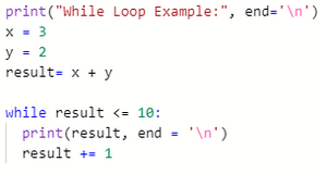
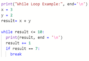
A while loop executes the code within the loop so long as the condition is true. In Figure 5, the while loop will continuously print the result on a new line and add 1 to the result so long as the result is less than or equal to 10.
A break statement is used to break a loop regardless of the condition (Figure 6).
For Loops
A for loop is used for iterating over a set sequence. The sequence can be a list, tuple, dictionary, set, or string. In Figure 7, the for loop will print each character in the string random_word with a space in between each character. Similar to the while loop, a for loop can be broken early with a break statement.
Comments
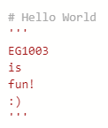
Comments within code are typically used to explain the code and make the code more readable and easier to troubleshoot when errors arise. Line comments begin with a # and can only span a single line. Block comments begin and end with a ’’’ and can span multiple lines (Figure 8).
Computer Vision (CV)
Computer vision is an area of artificial intelligence (AI) that allows computers and systems to measure data from visual inputs and produce outputs based on that data. The OpenCV library is an extensive open-source library used for computer vision. OpenCV contains interfaces for multiple programming languages.
OpenCV allows image/video processing and display, object detection, geometry-based monocular or stereo computer vision, computational photography, machine learning and clustering, and CUDA acceleration. With this functionality, many applications are possible including facial recognition, street view image stitching, and driverless car navigation.
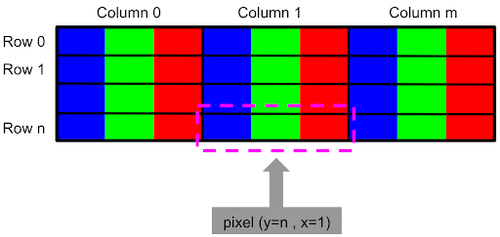
In OpenCV, color images are represented as three-dimensional arrays. An image consists of rows of pixels, and each pixel is represented by an array of values representing its color in BGR (Blue, Green, Red) format (Figure 9).
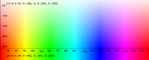
The array can be transcribed into the color’s specific hue saturation value (HSV). The HSV model describes colors similar to how the human eye tends to perceive color. This format is more suitable for color detection purposes (Figure 10).
cv2.cvtColor()
cv2.cvtColor(frame, conversion code) is a method used to convert an image from one color space to another. In the OpenCV Library, there are over 150 different color-space conversion codes. The one used in this lab is cv2.COLOR_BGR2HSV, which converts an image from the default BGR format to the desired HSV format.
cv2.inRange()
cv2.inRange(frame, lower bound, upper bound) is a method used to identify pixels in the frame that fall within the range of values defined by the lower and upper boundaries. This command outputs a binary mask where white pixels represent areas that fall within the range, and black pixels represent areas that do not fall within the range. The right panel in Figure 11 shows the output for the cv2.inRange() method using the command orange_mask = cv2.inRange(nemo,lower,upper). The bright orange pixels fall within the range specified and have a corresponding white value in the output.
cv2.bitwise_and()
cv2.bitwise_and(frame, frame, mask = mask) is a bitwise AND operation that delegates in making the frame only retain what is determined by the set mask. Only pixels in the frame with a corresponding white value in the mask would be preserved. The rightmost panel in Figure 12 shows the output of the command cv2.bitwise_and(nemo, nemo, mask=orange_mask).
cv2.bitwise_or()
cv2.bitwise_or(frame1, frame2) is a bitwise OR operation that delegates in combining multiple frames so that the output retains non-zero pixels from either frame.
cv2.imshow()
cv2.imshow(window name, image) is used to display a given image in a window. The name of the window is given by the first parameter in the command. The window automatically displays in the same size as the image.
NumPy
Numerical Python (NumPy) is a Python library used primarily for working with arrays. The library also contains functions for mathematical purposes, such as linear algebra, Fourier transformation, and matrices. In this lab, the NumPy command used is np.array.
np.array()
np.array() creates an array object of the class N-dimensional NumPy array or numpy.ndarray. A list, tuple, or number can be entered in the parentheses to turn the data type into an array.
USB Camera
The USB Camera Module is a camera that can be used to capture high-resolution and high-definition images and video. The module’s library features commands to use the camera within code and modify how the camera outputs the frame rate, resolution, and timing of the image or video it is capturing. The camera module’s coding library (picamera) is automatically installed onto a Raspberry Pi once the camera is enabled and the Raspberry Pi is rebooted.
camera.set (cv2.CAP_PROP_FRAME_WIDTH, width) or camera.set(cv2.CAP_PROP_FRAME_HEIGHT, height)
camera.set() sets a specific resolution (width/height) for the frame in teh video stream. The maximum resolution for still photos is 2592 x 1944 pixels and 1920 x 1080 pixels for video recording. The minimum resolution is 64 x 64 pixels.
camera.read()
camera.read() reads the current frame from the camera.
camera.cv2.VideoCapture()
camera = cv2.VideoCapture(0) declares camera as an object for all function calls later and enables the camera module to capture an image in video format.
Raspberry Pi Setup
Before using a Raspberry Pi, the Raspberry Pi must be prepared with a formatted SD card with Raspberry Pi OS and the correct programming library packages installed. For this lab, these steps have been done. A more detailed explanation of the Raspberry Pi Setup can be found in the Appendix.
Servo Motor Setup
Continuous vs. Positional Servo Motor
A servo motor is a compact actuation device with high power output and energy efficiency. There are two kinds of servo motors used for common applications - continuous rotation and positional rotation servos. A continuous servo motor has a shaft that spins continuously allowing definite control over its speed and direction. A positional servo motor can only turn over a range of 180 degrees (90 degrees in each direction), allowing precise control over its position (Figure 13).
Programming Servo Motors (Raspberry Pi)
The following commands are used to program a continuous rotation servo motor once it’s wired to the GPIO pins on the Raspberry Pi:
GPIO.setmode(mode)
GPIO.setmode(mode) is used to dictate how the GPIO pins on the Pi are referenced in the program. Following are the two options for GPIO mode:
- GPIO.BOARD - Refers to the pins by the physical position of the pin on the board
- GPIO.BCM - Refers to the pins by the Broadcom SOC channel number, which is an intrinsically defined system that differs for various versions of the Pi (refer to Raspberry Pi GPIO Pinout)
In this lab, we will be referencing the GPIO pins with the GPIO.BCM method.
GPIO.setup(pin, mode)
GPIO.setup(servoPin, mode) sets the servoPin to either an input or output. The corresponding options for the mode are GPIO.IN and GPIO.OUT
GPIO.PWM(servoPin, frequency)
PWM stands for Pulse Width Modulation. Servos use a pulse-width modulated input signal that defines the state of rotation or position of the servo shaft. GPIO.PWM(servoPin, frequency) initializes PWM to a servo pin and a certain constant frequency.
pwm.start(duty cycle)
pwm.start(duty cycle) begins servo rotation with a specified duty cycle value, which is a measure of the speed and direction of rotation of the shaft. For the continuous rotation servos used in this lab, the shaft rotates:
- Clockwise for a duty cycle value of less than 14
- Counterclockwise for a duty cycle value of 14 or greater
pwm.stop()
pwm.stop() ceases servo motor rotation entirely.
GPIO.cleanup()
GPIO.cleanup() resets the ports and pins to the default state.
Materials and Equipment
- Raspberry Pi with SD card
- USB Camera
- Monitor with micro HDMI to HDMI cable
- USB keyboard
- USB mouse
- Power supply
Procedure
Ensure that the Raspberry Pi is connected to a power supply and a monitor. Verify that the camera module and the USB mouse and keyboard are plugged into their corresponding ports on the Raspberry Pi.
Setting up the Raspberry Pi
Before getting started with this procedure, ensure that an SD card with Raspberry Pi OS is inserted into the designated slot on the Raspberry Pi.
- Connect a USB mouse and keyboard to the Pi.
- Using a micro HDMI cable, connect the board to a monitor.
- If required, connect an audio output device to the board using the audio jack.
- Connect the board to a power supply using the Raspberry Pi charger.
- Sign into the guest wifi (If the wifi sign doesn’t show up, go to nyu.edu or type in "8.8.8.8" in the browser.
Raspberry Pi will boot up and the monitor will display the desktop. This concludes the Pi setup.
Setting up the USB Camera
The following steps outline the procedure for connecting the camera module.
- Locate the USB port and insert the USB Camera, as shown in Figure 14.Ensure the Raspberry Pi is powered off.
- Turn on the Raspberry Pi, and open the terminal on the top left corner of the screen.
- Enter the following: "sudo apt-get install fswebcam" to install the webcam library.
- Enter the following: "lsusb" and check that USB is reading the camera.
- Enter the following: "fswebcam testpic.jpg" to take a test picture.
- Open the file explorer on the top left, and verify that the test picture was successful.
Part 1: Wiring the Servo Motor
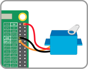
- Wire the servo motor according to the following diagram. Make sure to wire the servo pin to GPIO 17 on the Raspberry Pi, as shown in Figure 15.
Part 2: Color Detection using USB Camera and Python-OpenCV
In this part, a Python script that isolates red and green colors from a live video captured by the camera module will be developed and this output will be used to create a prototype of a traffic light detection system.
- Download the Python script for color detection using OpenCV. Open the camera module with the Thonny Python Editor installed on the Raspberry Pi.
- There are missing components in the program. Complete the code following the instructions outlined in the next steps.
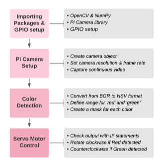
- The code is divided into four sections. Figure 16 shows the workflow for this lab.
- Section 1 includes commands for importing all necessary packages and setting up the GPIO pins on the Pi.
- Section 2 sets up the camera module so it captures a continuous video.
- Section 3 contains code for color detection and isolation for red and green colors.
- Section 4 integrates the servo motor with the color detection output such that the servo rotates clockwise when red is detected, counterclockwise when green is detected, and stops rotating when neither red nor green is detected.
- Section 1 of the code consists of packages that are to be included. Type the code in Figure 17 to import the required packages into the Python module. (Note: code is case sensitive, copy the code exactly as it is shown below)
- OpenCV represents images as NumPy arrays. Lines 3-5 import OpenCV, NumPy, and Picamera2 libraries. The images obtained from the camera module must be in an array format so Line 6 is included.Line 7 imports the Raspberry Pi GPIO library.
- Assign a variable for the servo pin. Based on the wiring diagram, the servo should be wired to pin 17 on the Raspberry Pi.
- Set GPIO mode to GPIO.BCM
- Set the mode for the servo pin as output. This completes section 1 of the code.
- Section 2 of the code sets up the camera module. The while(True): condition creates an infinite loop so that the code re-runs automatically to perform color detection on a set of objects. In the body of the while loop, type out a command for each of the following tasks using the background information of the camera module commands as reference.
- Get the code approved by a TA and move to the next step.
- Section 3 is image processing. The next step is to capture a continuous video array with the camera. This is achieved by using the camera.read() command as shown on Line 23 in the figure below. Line 27 converts every frame captured by the camera module from a BGR color format to an HSV format, ready to be manipulated with OpenCV to perform color detection.
- Next is to perform color detection for red and green colors. Since it is easier to identify these colors with their HSV, each frame is converted from the default BGR format to the HSV format. Line 26 in Figure 19 performed this task using the cv2.cvtColor method. The newly created HSV frame (stored as variable hsvFrame) will now be used for color detection.
- The segment of code in Figure 19 will isolate red from the video. Lines 29-30 define the lower and upper boundaries of the range of HSV values within which the color would be classified as red. These values might have to be adjusted based on lighting and exposure conditions.
- Line 31, identifies all the pixels in the video that fall within the specified range by defining a variable red_mask, and using the cv2.InRange method using red_lower and red_upper as boundaries. This line outputs a binary mask where white pixels represent areas that fall within the range, and black pixels represent areas that do not.
- Line 32 applies the mask over the video to isolate red using the cv2.bitwise_and method taking frame as the input, and outputting frame using red_mask as the mask. This line outputs the frame so that only pixels that have a corresponding white value in the mask are shown.
- Insert code that will be used to isolate green from the video. Use the lower boundary values [20,40,60] and upper boundary values [102, 255, 255] to define the range.
- To isolate both red and green from the video at once, combine result_red and result_green. Think about how this could be achieved and type out the correct command in Line 40 (Figure 20). Which bitwise operation should be used to show pixels where either red or green are present?
- To display the final result (Line 42), type a line of code that creates a new window named "Red and Green Detection in Real-Time" which will display the final output. Use the cv2.imshow method.
- This concludes Section 3 of the program. Get the code approved by a TA and move to Section 4.
- Lines 46-63 represent the final section of the program. The objective of this section is to integrate the color detection output with servo rotation. The servo would rotate clockwise when a red object is detected, counterclockwise when a green object is detected, and stop rotation when neither red nor green is detected.
- Line 46 dictates that every time the key ‘q’ is pressed, the camera closes and stops capturing new frames. The final frame is checked for the presence of red and green using if statements (lines 47-59).
- The following conditions are implemented for detecting red color in the video (lines 47-48) the frame should have more red pixels than green, and the number of red pixels should be at least 25% of the total number of pixels. The cv2.countNonZero method is used on red_mask to obtain the number of red pixels.
- On line 50, insert a command to start servo rotation with a 5% duty cycle (using the commands discussed in earlier sections). This corresponds to clockwise rotation.
- Insert the following conditions for detecting green color (line 52) the frame should have more green pixels than red, and the number of green pixels should be at least 25% of the total number of pixels.
- On line 55, insert a command to start servo rotation with a 55% duty cycle. This corresponds to counterclockwise rotation.
- On line 59, insert a command to stop servo rotation.
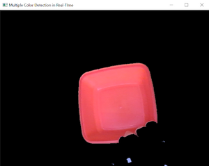
- Run the Python script and place the red and green objects provided by the TAs in front of the camera module. Observe how the specified colors are isolated from the video output. Press the q key on the keyboard to pause the video at a specific frame and observe the output print statements. Figure 22 displays what the final output would look like when a red object is held up to the camera module.
This concludes the procedure for this workshop.
Assignment
Individual Lab Report
There is no lab report for Lab 3.
Team PowerPoint Presentation
There is no team presentation for Lab 3.
References
Raspberry Pi Foundation. “Getting Started with Raspberry Pi.” Raspberry Pi Foundation. Raspberry Pi Foundation, (n.d.). Retrieved 5 August 2021. https://projects.raspberrypi.org/en/projects/raspberry-pi-getting-started
Raspberry Pi Foundation. “Usage - Raspberry Pi Documentation.” Raspberry Pi Foundation. Raspberry Pi Foundation, (n.d.). Retrieved 5 August 2021. https://www.raspberrypi.org/documentation/usage/
IBM Corp. “What is Computer Vision.” IBM. International Business Machines Corporation, (n.d.). Retrieved 5 August 2021 https://www.ibm.com/topics/computer-vision
Real Python. (2020, November 7). Image segmentation using color spaces in OpenCV and Python. Real Python. https://realpython.com/python-opencv-color-spaces/. Retrieved 9 August 2021
Appendix
Installing Raspberry Pi OS on an SD card
This section outlines the procedure for installing an operating system on the Raspberry Pi using the Raspberry Pi Imager. A formatted SD card and a computer with an SD card reader are required to follow this procedure.
- Download the latest version of Raspberry Pi Imager and install it on a computer.
- Connect an SD card to the computer.
- Before this step, the SD card must be formatted to FAT32.
- Open Raspberry Pi Imager and choose the operating system. For most general uses of a Raspberry Pi, Raspberry Pi OS (32-bit) should suffice.
- Click on Storage and choose the SD card to write the image to.
- Click on Write to install the operating system image on the SD card.
Installing OpenCV & Other Packages
This section outlines the procedure for installing the Python packages used in this lab.
- OpenCV
- NumPy
- PiCamera with [array] submodule
- Open a terminal window by clicking the black monitor icon on the taskbar (Figure 25).
- Before installing the required packages, install PIP, update the system, and install Python 3 using the commands PIP for python3 - sudo apt-get install python 3-pip, sudo apt-get update && sudo apt-get upgrade, and sudo apt-get install python3.
- To install OpenCV, NumPy, and PiCamera packages, type out the following commands sudo pip3 install opencv-python, sudo pip3 install numpy, and sudo pip3 install picamera[array].
- Optionally, to utilize the GPIO pins on the Raspberry Pi, install the GPIO library using the following command sudo pip-3.2 install RPi.GPIO.
