Difference between revisions of "VEX Building Guide"
| (24 intermediate revisions by the same user not shown) | |||
| Line 1: | Line 1: | ||
==Goals for this Guide== | ==Goals for this Guide== | ||
*Specify restrictions on the VEX | *Specify restrictions on the VEX robots | ||
*Basic introduction to kit components | *Basic introduction to kit components | ||
**What are the parts and how to use them correctly | **What are the parts and how to use them correctly | ||
| Line 12: | Line 12: | ||
==Restrictions== | ==Restrictions== | ||
*Size Limitation | *Size Limitation | ||
**A typical VEX | **A typical VEX robot should be smaller than 15x15 in. (slightly less than a tile). | ||
**There’s no limitation in height, but if you plan to go for the extra credit ramp, there is a soft limitation in height. | **There’s no limitation in height, but if you plan to go for the extra credit ramp, there is a soft limitation in height. | ||
*Robot Design | *Robot Design | ||
**No projectile or anything too crazy | **No projectile or anything too crazy | ||
**No jumping off the ramps for path planning | **No jumping off the ramps for path planning | ||
* | *For LAZ, a claw set MUST be attached to the robot. Sensors are optional. | ||
'''<span style="color: red;">NOTICE: Your VEX robot CANNOT be identical to the traditional VEX clawbot. There must be something different and unique about your robot.</span>''' | '''<span style="color: red;">NOTICE: Your VEX robot CANNOT be identical to the traditional VEX clawbot. There must be something different and unique about your robot.</span>''' | ||
==Components== | ==Components== | ||
===Hardware=== | |||
====Nuts, Screws, and Wrench==== | |||
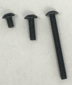
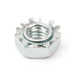
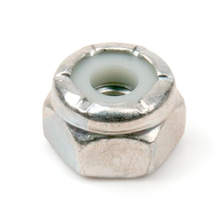
*The Vex Kit that you received contains many materials, such as nuts, screws, and standoffs, designed to connect two or more bodies. The ''black screws'' are found in three sizes (Figure 2-1) and must be tightened by one of the ''keps nuts'' or ''nylock nuts'' (Figure 2-2). | *The Vex Kit that you received contains many materials, such as nuts, screws, and standoffs, designed to connect two or more bodies. The ''black screws'' are found in three sizes (Figure 2-1) and must be tightened by one of the ''keps nuts'' or ''nylock nuts'' (Figure 2-2). | ||
[[File:VEX_Building_Guide_1.png|thumb|250px|frame|center| Figure 2-1: Black Screws]] | |||
[[File:VEX_Building_Guide_2.png|thumb|250px|frame|center| Figure 2-2: Keps Nut]] | |||
[[File:VEX_Building_Guide_3.png|thumb|250px|frame|center| Figure 2-3: Nylock Nut]] | |||
*Keps Nuts are used for strong, yet removable bonds. | *Keps Nuts are used for strong, yet removable bonds. | ||
*Nylock Nuts are used for stronger, permanent bonds. | *Nylock Nuts are used for stronger, permanent bonds. | ||
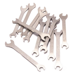
*To remove a nut, you need the help of the open end wrench (Figure 2-4) to keep it from turning. It provides grip and mechanism advantage in applying torque. The wrench you are given fits all nuts and standoffs. | *To remove a nut, you need the help of the open end wrench (Figure 2-4) to keep it from turning. It provides grip and mechanism advantage in applying torque. The wrench you are given fits all nuts and standoffs. | ||
*The second type of screw that you will see in your kit is the locking screw. Again, these golden screws come in a few sizes. They have a smaller width than the black screws, so they CANNOT be tightened by the | |||
Keps Nuts. These screws will be mainly used to secure the motors (Figure 2-5) into place. | [[File:VEX_Building_Guide_4.png|thumb|250px|frame|center| Figure 2-4: Open End Wrenches]] | ||
*The second type of screw that you will see in your kit is the locking screw. Again, these golden screws come in a few sizes. They have a smaller width than the black screws, so they CANNOT be tightened by the Keps Nuts. | |||
*These screws will be mainly used to secure the motors (Figure 2-5) into place. | |||
[[File:VEX_Building_Guide_5.png|thumb|250px|frame|center| Figure 2-5: Locking Screw with Motors]] | |||
*The screws can be tightened with the help of hex keys (Figure 2-6). The hex keys come in two different sizes (one with diameter 3/32” and one with diameter 5/64”), corresponding to the dimensions of the hole in screws. So try each hex key until the hex key’s end perfectly fits inside the drive of the screw. | *The screws can be tightened with the help of hex keys (Figure 2-6). The hex keys come in two different sizes (one with diameter 3/32” and one with diameter 5/64”), corresponding to the dimensions of the hole in screws. So try each hex key until the hex key’s end perfectly fits inside the drive of the screw. | ||
[[File:VEX_Building_Guide_6.png|thumb|250px|frame|center|Figure 2-6: Hex Keys]] | |||
====Standoffs, Shaft Couplers, and Motor Post==== | |||
*Instead of Keps Nuts, standoffs can also be used to secure screws in place. Standoffs are used to connect two different parts through screws or shafts, depending on the type of standoff. | *Instead of Keps Nuts, standoffs can also be used to secure screws in place. Standoffs are used to connect two different parts through screws or shafts, depending on the type of standoff. | ||
*The screw standoff is used to connect two black screws (Figure 2-7). The shaft counterpart is called the shaft coupler. Motor posts (Figure 2-8) are used to connect shaft couplers to motors. | *The screw standoff is used to connect two black screws (Figure 2-7). The shaft counterpart is called the shaft coupler. Motor posts (Figure 2-8) are used to connect shaft couplers to motors. | ||
[[File:VEX_Building_Guide_7.png|thumb|250px|frame|center|Figure 2-7: Screw Standoffs]] | |||
< | [[File:VEX_Building_Guide_8.png|thumb|250px|frame|center|Figure 2-8: Shaft Couplers and Motor Posts]] | ||
'''<span style="color: red;">Note that standoffs and the couplers are NOT completely secured and can disassemble easily. Standoffs and couplers should only be used to connect parts that are already secured in place.</span>''' | |||
====Shafts and Shaft Collars==== | |||
*Your kit contains square shafts of two different lengths. The shafts are used by the motors to turn the gears and your wheels. Shafts can be secured in place by shaft collars (Figure 2-9). | *Your kit contains square shafts of two different lengths. The shafts are used by the motors to turn the gears and your wheels. Shafts can be secured in place by shaft collars (Figure 2-9). | ||
| Line 50: | Line 66: | ||
*Use two shaft collars to completely lock a part in place. | *Use two shaft collars to completely lock a part in place. | ||
[[File:VEX_Building_Guide_9.png|thumb|480px|frame|center|Figure 2-9: Gear Secured in a Square Shaft by Two Shaft Collars]] | |||
====Bearing Flat and Bearing Attachment Rivet==== | |||
*The square shafts are inherently smaller than the square holes in the structural metal pieces. Due to this, there will be rattling once the motor starts spinning. | *The square shafts are inherently smaller than the square holes in the structural metal pieces. Due to this, there will be rattling once the motor starts spinning. | ||
*In order to minimize the rattling, bearing flats are used in conjunction with the structural part because the bearing flat’s hole is much more accommodating of the shaft’s size. | *In order to minimize the rattling, bearing flats are used in conjunction with the structural part because the bearing flat’s hole is much more accommodating of the shaft’s size. | ||
*The unused holes of the bearing flat can be tightly and smoothly secured with bearing attachment rivets | *The unused holes of the bearing flat can be tightly and smoothly secured with bearing attachment rivets(Figure 2-10, Figure 2-11). | ||
(Figure 2-10, Figure 2-11). | |||
[[File:VEX_Building_Guide_10.png|thumb|250px|frame|center|Figure 2-10: From Bottom to Top: Square Shaft, Bearing Flat, and Bearing Attachment Rivet]] | |||
[[File:VEX_Building_Guide_11.png|thumb|250px|frame|center|Figure 2-11: Bearing Flat Contraption]] | |||
====Spacers==== | |||
*Spacers are used in order to properly position certain components of your robot, such as a gear. They come in different sizes and types, depending on the displacement needed. | *Spacers are used in order to properly position certain components of your robot, such as a gear. They come in different sizes and types, depending on the displacement needed. | ||
*A regular spacer (Figure 2-12) can be put in anywhere in a shaft, while wheel spacers are designed to | *A regular spacer (Figure 2-12) can be put in anywhere in a shaft, while wheel spacers are designed to lock the wheels on the shafts. | ||
lock the wheels on the shafts. | *Bearing flats and shaft collars can also be used as spacers, if necessary. | ||
[[File:VEX_Building_Guide_12.png|thumb|250px|frame|center|Figure 2-12: Regular Spacer]] | |||
[[File:VEX_Building_Guide_13.png|thumb|250px|frame|center|Figure 2-13: Wheel Spacers]] | |||
====Motors and High-Speed Gear==== | |||
*The 2-Wire Motor 393 is the primary actuator you have for VEX | *The 2-Wire Motor 393 is the primary actuator you have for VEX. It can be used to build a rotational mechanism, drive bases, rotational joints, conveyor belts - anything that can spin. It can be configured to a “high speed” version with the help of the high-speed gear. Follow the Gear Change Procedure (http://cmra.rec.ri.cmu.edu/products/cortex_video_trainer/lesson/media_files/2_wire_393_motor_ig.pdf) to increase your output speed by 60%. | ||
increase your output speed by 60%. | |||
[[File:VEX_Building_Guide_14.png|thumb|250px|frame|center|Figure 2-14: 2-Wire Motor]] | |||
====Claw Set==== | |||
*Each VEX kit is given a claw set that is pre-assembled and ready to grab and manipulate objects. | *Each VEX kit is given a claw set that is pre-assembled and ready to grab and manipulate objects. | ||
*It has a motor attached to the top of the claw bracket and is able to hold from a delicate feather to a | *It has a motor attached to the top of the claw bracket and is able to hold from a delicate feather to a 20 oz soda can. | ||
20 oz soda can. | *The main use of the claw is to grab and carry the plant sample back to the starting tile. | ||
* | *Use this link to access the guide on how to assemble a claw set: https://content.vexrobotics.com/docs/276-2600-Claw-Assembly.pdf | ||
[[File:VEX_Building_Guide_15.png|thumb|250px|frame|center|Figure 2-15: Pre-Assembled Claw Set]] | |||
====Zip Ties==== | |||
*Zip ties are used to secure parts together are unable to be fixed in place with the conventional hardware components. | *Zip ties are used to secure parts together are unable to be fixed in place with the conventional hardware components. | ||
*Zip ties are more flexible in areas of usage but are limited by the lack of secureness compared to nuts and screws. There are zip ties of two different lengths in the kit. | *Zip ties are more flexible in areas of usage but are limited by the lack of secureness compared to nuts and screws. There are zip ties of two different lengths in the kit. | ||
*In order to tie a zip tie, wrap the long stem of the zip tie around such that the tail of the zip tie is inserted into the flat side of the head. Pull the tail of the zip tie into the desired length (Figure 2- | *In order to tie a zip tie, wrap the long stem of the zip tie around such that the tail of the zip tie is inserted into the flat side of the head. Pull the tail of the zip tie into the desired length(Figure 2-16). If done correctly, the zip tie cannot be undone and can only be tightened. | ||
[[File:VEX_Building_Guide_16.png|thumb|250px|frame|center|Figure 2-16: Zip Tie]] | |||
==Motion== | ==Motion== | ||
==Gear Train== | |||
*The Vex robot that you build will have to travel on the course. In order for the wheels to move, the wheel either has to be directly connected to the motor with a shaft or indirectly connected to the motor with a gear train. | *The Vex robot that you build will have to travel on the course. In order for the wheels to move, the wheel either has to be directly connected to the motor with a shaft or indirectly connected to the motor with a gear train. | ||
*A gear train is made of a series of interlocking gears, either of varying sizes or similar sizes, with one gear of the gear train connected to an input source, such as a motor. As the motorized gear spins, | *A gear train is made of a series of interlocking gears, either of varying sizes or similar sizes, with one gear of the gear train connected to an input source, such as a motor. As the motorized gear spins, every single gear in the gear train also turns. | ||
every single gear in the gear train also turns. A wheel could be connected to any adjacent gears in order to turn that wheel as well. The length of the gear train depends on the distance between the motor and the desired wheel. Keep in mind that an odd number of gears in the gear train will cause the driven gears to spin in the same direction and an even number of gears in the gear train will cause the driven gears to spin in the opposite direction. Therefore, it is essential that gear trains have an odd number of gears in order to spin correctly. Gear trains are advantageous if both sets of wheels are traction wheels in order to have a smoother turn. | *A wheel could be connected to any adjacent gears in order to turn that wheel as well. The length of the gear train depends on the distance between the motor and the desired wheel. Keep in mind that an odd number of gears in the gear train will cause the driven gears to spin in the same direction and an even number of gears in the gear train will cause the driven gears to spin in the opposite direction. Therefore, it is essential that gear trains have an odd number of gears in order to spin correctly. Gear trains are advantageous if both sets of wheels are traction wheels in order to have a smoother turn. | ||
[[File:VEX_Building_Guide_17.png|thumb|480px|frame|center|Figure 3-1: Simple Gear Train with Idler(NO EFFECT on Gear ratio)]] | |||
*Another method to induce motion is to let one set of wheels be freely spun due to the friction caused by another set of wheels that are powered by a motor. In this case, no gear train is used. This is advantageous if one set of wheels is omni-wheels that can freely turn. But for VEX MRR, having a gear train is recommended as we plan the robot to climb up a hill that is more than 30 degrees. Besides, the robot would perform point turn better with the help of the gear train. | *Another method to induce motion is to let one set of wheels be freely spun due to the friction caused by another set of wheels that are powered by a motor. In this case, no gear train is used. This is advantageous if one set of wheels is omni-wheels that can freely turn. But for VEX MRR, having a gear train is recommended as we plan the robot to climb up a hill that is more than 30 degrees. Besides, the robot would perform point turn better with the help of the gear train. | ||
==Gear Ratio== | |||
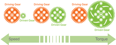
*Making a gear ratio is one of the easiest ways to change the Mechanical Advantage in a mechanism or system to achieve the desired speed or torque. It expresses the relationship between a driving gear(the gear connected to the input power source, such as a motor) and a driven gear(the gear connected to the output, such as a wheel) in a system. | *Making a gear ratio is one of the easiest ways to change the Mechanical Advantage in a mechanism or system to achieve the desired speed or torque. It expresses the relationship between a driving gear(the gear connected to the input power source, such as a motor) and a driven gear(the gear connected to the output, such as a wheel) in a system. | ||
[[File:VEX_Building_Guide_18.png|thumb|480px|frame|center|Figure 3-2: Different Gear Ratio]] | |||
*When you have a system with a driving gear that is LARGER than the driven gear, you will increase the speed and decrease the torque. Otherwise, if the driving gear is SMALLER than the driven gear, you will increase the torque and decrease the speed. | *When you have a system with a driving gear that is LARGER than the driven gear, you will increase the speed and decrease the torque. Otherwise, if the driving gear is SMALLER than the driven gear, you will increase the torque and decrease the speed. | ||
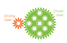
*Gear ratio is expressed in this way: (Driving Gear Teeth) : (Driven Gear Teeth), and gear | *Gear ratio is expressed in this way: (Driving Gear Teeth):(Driven Gear Teeth), and gear reduction(another mathematical expression that describes the relationship) is expressed in reverse:(Driven Gear Teeth) /(Driven Gear Teeth). The following are a 12-teeth driving gear with a 36-teeth driven gear. | ||
reduction(another mathematical expression that describes the relationship) is expressed in reverse: | |||
(Driven Gear Teeth) / (Driven Gear Teeth). The following are a 12-teeth driving gear with a 36-teeth | |||
driven gear. | |||
[[File:VEX_Building_Guide_19.png|thumb|480px|frame|center|Figure 3-3: Example Driving Gear and Driven Gear]] | |||
The gear ratio is 12:36, and the gear reduction is 36/12 = 3/1 = 3. That means that the output (driven | The gear ratio is 12:36, and the gear reduction is 36/12 = 3/1 = 3. That means that the output (driven | ||
gear) shaft is 3 times slower than the input (driving gear) shaft and has 3 times as much torque. | gear) shaft is 3 times slower than the input (driving gear) shaft and has 3 times as much torque. | ||
Please refer to [[Robot Construction Tips]] for Center of Gravity and Drive Train. | |||
==Chart of the Clawbot Pieces== | ==Chart of the Clawbot Pieces== | ||
| Line 133: | Line 164: | ||
**Weight distribution REALLY matters. Due to the importance of the center of gravity to the orientation and balance of the robot, it is important to consider where the center of gravity is when the robot is on unbalanced terrains, such as a ramp, and when the robot’s structure is being manipulated, such as a moving claw. | **Weight distribution REALLY matters. Due to the importance of the center of gravity to the orientation and balance of the robot, it is important to consider where the center of gravity is when the robot is on unbalanced terrains, such as a ramp, and when the robot’s structure is being manipulated, such as a moving claw. | ||
Here are a number of suggestions for the weight distribution: | <b>Here are a number of suggestions for the weight distribution:</b> | ||
*Generally, the center of gravity should be low on the robot in order for the robot to be stable on flat ground. If the center of gravity is too high, the robot might tilt and fall over. | *Generally, the center of gravity should be low on the robot in order for the robot to be stable on flat ground. If the center of gravity is too high, the robot might tilt and fall over. | ||
*In addition, due to the effects of gravity, if the robot traverses up a ramp, the back of the robot contributes to the center of gravity more than the front of the robot. Thus it is optimal to have the center of gravity near the front of the robot in order to balance the robot on the hill. Otherwise, the robot would either not have enough power to travel up the hill. | *In addition, due to the effects of gravity, if the robot traverses up a ramp, the back of the robot contributes to the center of gravity more than the front of the robot. Thus it is optimal to have the center of gravity near the front of the robot in order to balance the robot on the hill. Otherwise, the robot would either not have enough power to travel up the hill. | ||
*Likewise, if the robot is traveling down a hill, the center of gravity should be adjusted towards the back of the robot in order to account for the effects of gravity. It is important that the center of gravity is aligned with the location of the motors in these scenarios or else the robot would tip over. | *Likewise, if the robot is traveling down a hill, the center of gravity should be adjusted towards the back of the robot in order to account for the effects of gravity. It is important that the center of gravity is aligned with the location of the motors in these scenarios or else the robot would tip over. | ||
Latest revision as of 20:28, 3 February 2021
Goals for this Guide
- Specify restrictions on the VEX robots
- Basic introduction to kit components
- What are the parts and how to use them correctly
- Choice of pieces given different building purposes
- Robots motion
- Gear train
- Gear ratio
- Chart of clawbot pieces
- Tips on troubleshooting the design
Restrictions
- Size Limitation
- A typical VEX robot should be smaller than 15x15 in. (slightly less than a tile).
- There’s no limitation in height, but if you plan to go for the extra credit ramp, there is a soft limitation in height.
- Robot Design
- No projectile or anything too crazy
- No jumping off the ramps for path planning
- For LAZ, a claw set MUST be attached to the robot. Sensors are optional.
NOTICE: Your VEX robot CANNOT be identical to the traditional VEX clawbot. There must be something different and unique about your robot.
Components
Hardware
Nuts, Screws, and Wrench
- The Vex Kit that you received contains many materials, such as nuts, screws, and standoffs, designed to connect two or more bodies. The black screws are found in three sizes (Figure 2-1) and must be tightened by one of the keps nuts or nylock nuts (Figure 2-2).
- Keps Nuts are used for strong, yet removable bonds.
- Nylock Nuts are used for stronger, permanent bonds.
- To remove a nut, you need the help of the open end wrench (Figure 2-4) to keep it from turning. It provides grip and mechanism advantage in applying torque. The wrench you are given fits all nuts and standoffs.
- The second type of screw that you will see in your kit is the locking screw. Again, these golden screws come in a few sizes. They have a smaller width than the black screws, so they CANNOT be tightened by the Keps Nuts.
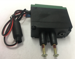
- These screws will be mainly used to secure the motors (Figure 2-5) into place.
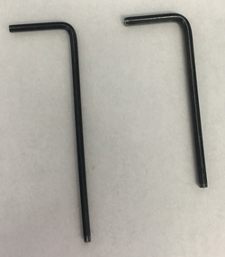
- The screws can be tightened with the help of hex keys (Figure 2-6). The hex keys come in two different sizes (one with diameter 3/32” and one with diameter 5/64”), corresponding to the dimensions of the hole in screws. So try each hex key until the hex key’s end perfectly fits inside the drive of the screw.
Standoffs, Shaft Couplers, and Motor Post
- Instead of Keps Nuts, standoffs can also be used to secure screws in place. Standoffs are used to connect two different parts through screws or shafts, depending on the type of standoff.
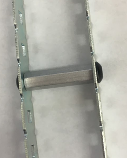
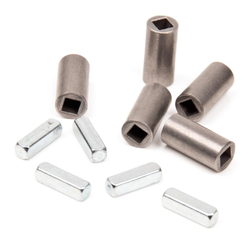
- The screw standoff is used to connect two black screws (Figure 2-7). The shaft counterpart is called the shaft coupler. Motor posts (Figure 2-8) are used to connect shaft couplers to motors.
Note that standoffs and the couplers are NOT completely secured and can disassemble easily. Standoffs and couplers should only be used to connect parts that are already secured in place.
Shafts and Shaft Collars
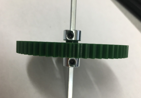
- Your kit contains square shafts of two different lengths. The shafts are used by the motors to turn the gears and your wheels. Shafts can be secured in place by shaft collars (Figure 2-9).
- Shaft collars can be tightened with the thinner/longer (3/32”) hex key.
- Use two shaft collars to completely lock a part in place.
Bearing Flat and Bearing Attachment Rivet
- The square shafts are inherently smaller than the square holes in the structural metal pieces. Due to this, there will be rattling once the motor starts spinning.
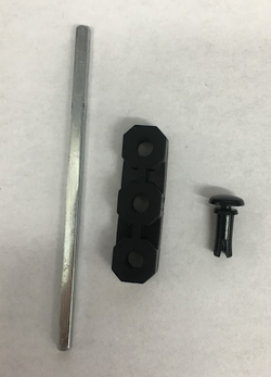
- In order to minimize the rattling, bearing flats are used in conjunction with the structural part because the bearing flat’s hole is much more accommodating of the shaft’s size.
- The unused holes of the bearing flat can be tightly and smoothly secured with bearing attachment rivets(Figure 2-10, Figure 2-11).
Spacers
- Spacers are used in order to properly position certain components of your robot, such as a gear. They come in different sizes and types, depending on the displacement needed.
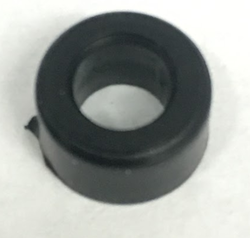
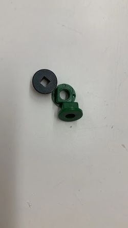
- A regular spacer (Figure 2-12) can be put in anywhere in a shaft, while wheel spacers are designed to lock the wheels on the shafts.
- Bearing flats and shaft collars can also be used as spacers, if necessary.
Motors and High-Speed Gear
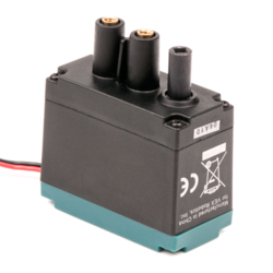
- The 2-Wire Motor 393 is the primary actuator you have for VEX. It can be used to build a rotational mechanism, drive bases, rotational joints, conveyor belts - anything that can spin. It can be configured to a “high speed” version with the help of the high-speed gear. Follow the Gear Change Procedure (http://cmra.rec.ri.cmu.edu/products/cortex_video_trainer/lesson/media_files/2_wire_393_motor_ig.pdf) to increase your output speed by 60%.
Claw Set
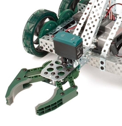
- Each VEX kit is given a claw set that is pre-assembled and ready to grab and manipulate objects.
- It has a motor attached to the top of the claw bracket and is able to hold from a delicate feather to a 20 oz soda can.
- The main use of the claw is to grab and carry the plant sample back to the starting tile.
- Use this link to access the guide on how to assemble a claw set: https://content.vexrobotics.com/docs/276-2600-Claw-Assembly.pdf
Zip Ties
- Zip ties are used to secure parts together are unable to be fixed in place with the conventional hardware components.
- Zip ties are more flexible in areas of usage but are limited by the lack of secureness compared to nuts and screws. There are zip ties of two different lengths in the kit.
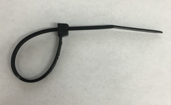
- In order to tie a zip tie, wrap the long stem of the zip tie around such that the tail of the zip tie is inserted into the flat side of the head. Pull the tail of the zip tie into the desired length(Figure 2-16). If done correctly, the zip tie cannot be undone and can only be tightened.
Motion
Gear Train
- The Vex robot that you build will have to travel on the course. In order for the wheels to move, the wheel either has to be directly connected to the motor with a shaft or indirectly connected to the motor with a gear train.
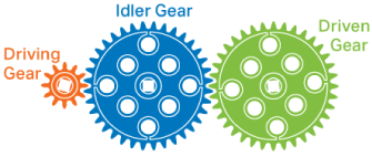
- A gear train is made of a series of interlocking gears, either of varying sizes or similar sizes, with one gear of the gear train connected to an input source, such as a motor. As the motorized gear spins, every single gear in the gear train also turns.
- A wheel could be connected to any adjacent gears in order to turn that wheel as well. The length of the gear train depends on the distance between the motor and the desired wheel. Keep in mind that an odd number of gears in the gear train will cause the driven gears to spin in the same direction and an even number of gears in the gear train will cause the driven gears to spin in the opposite direction. Therefore, it is essential that gear trains have an odd number of gears in order to spin correctly. Gear trains are advantageous if both sets of wheels are traction wheels in order to have a smoother turn.
- Another method to induce motion is to let one set of wheels be freely spun due to the friction caused by another set of wheels that are powered by a motor. In this case, no gear train is used. This is advantageous if one set of wheels is omni-wheels that can freely turn. But for VEX MRR, having a gear train is recommended as we plan the robot to climb up a hill that is more than 30 degrees. Besides, the robot would perform point turn better with the help of the gear train.
Gear Ratio
- Making a gear ratio is one of the easiest ways to change the Mechanical Advantage in a mechanism or system to achieve the desired speed or torque. It expresses the relationship between a driving gear(the gear connected to the input power source, such as a motor) and a driven gear(the gear connected to the output, such as a wheel) in a system.
- When you have a system with a driving gear that is LARGER than the driven gear, you will increase the speed and decrease the torque. Otherwise, if the driving gear is SMALLER than the driven gear, you will increase the torque and decrease the speed.
- Gear ratio is expressed in this way: (Driving Gear Teeth):(Driven Gear Teeth), and gear reduction(another mathematical expression that describes the relationship) is expressed in reverse:(Driven Gear Teeth) /(Driven Gear Teeth). The following are a 12-teeth driving gear with a 36-teeth driven gear.
The gear ratio is 12:36, and the gear reduction is 36/12 = 3/1 = 3. That means that the output (driven gear) shaft is 3 times slower than the input (driving gear) shaft and has 3 times as much torque.
Please refer to Robot Construction Tips for Center of Gravity and Drive Train.
Chart of the Clawbot Pieces
https://content.vexrobotics.com/docs/276-2600-Structure-Pieces-20140218.pdf
https://content.vexrobotics.com/docs/276-2600-Claw-Assembly.pdf
https://content.vexrobotics.com/docs/276-2600_VEXEDR_ClawbotKit_PartsList_Rev3.pdf
Tips for Troubleshooting
- Before building:
- In the design process, make sure that wires of all motors can reach the motor shield located in the center of the robot, or the motors will break easily.
- Calculate the gear ratio and consider the feasibility of the design before putting them all together.
- While building:
- Always remember to add wheel spacers before putting wheels on shafts, or the wheels won’t sit steady.
- Wrap all cables with electrics tapes to prevent them from touching each other or the metal frame of the robot.
- Zip ties can be used to tie up your wires and secure batteries in place.
- While testing:
- If the robot can not climb up the ramp, make sure you are using gear train and rubber bands to add traction to your wheels.
- If the tips of wires connected to the motor came off, solder another pin to the motor/ask a TA for help.
- Weight distribution REALLY matters. Due to the importance of the center of gravity to the orientation and balance of the robot, it is important to consider where the center of gravity is when the robot is on unbalanced terrains, such as a ramp, and when the robot’s structure is being manipulated, such as a moving claw.
Here are a number of suggestions for the weight distribution:
- Generally, the center of gravity should be low on the robot in order for the robot to be stable on flat ground. If the center of gravity is too high, the robot might tilt and fall over.
- In addition, due to the effects of gravity, if the robot traverses up a ramp, the back of the robot contributes to the center of gravity more than the front of the robot. Thus it is optimal to have the center of gravity near the front of the robot in order to balance the robot on the hill. Otherwise, the robot would either not have enough power to travel up the hill.
- Likewise, if the robot is traveling down a hill, the center of gravity should be adjusted towards the back of the robot in order to account for the effects of gravity. It is important that the center of gravity is aligned with the location of the motors in these scenarios or else the robot would tip over.
