Virtual Boom Construction Competition
Objective
The experimental objective of this lab is to design and construct a boom following the specifications provided on Fusion 360. The boom will be entered in a competition against other booms in the section. The designs will be judged by a competition ratio that uses boom mass, boom length, and the generated reaction force while deflecting 20 cm. The design with the highest competition ratio wins.
Overview
A boom is used to lift and move heavy objects, often objects that are much heavier than the boom itself. Distributing the weight of the object, or the load, being lifted over the length of the boom is the main problem in boom design. The design must consider the load the boom will be required to lift, how high the load will be lifted, and whether the boom will move or remain stationary while loaded.
Examples of Booms
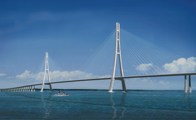
Certain types of bridges use booms. A cantilever bridge uses two booms extending from a common base. One type of cantilever bridge is a cable-stayed bridge (Figure 1).
The Ed Koch Queensboro Bridge is a double cantilever bridge (Figure 2). It has two bases with two booms extending from each base and the cantilevers placed end to end.
The Grand Bridge over Newtown Creek is a swing bridge, also known as a rotating bridge (Figure 3). This bridge has two booms mounted on a base that rotates.
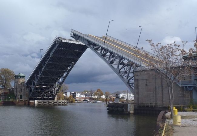
Figure 4 shows a bascule bridge, more commonly known as a drawbridge, where it is clear that the bridge uses a big, very flat boom.
Not all bridges are booms. Suspension bridges use a deck that is supported by steel cables, not booms. Examples of suspension bridges are the Brooklyn Bridge, Manhattan Bridge, Verrazano-Narrows Bridge, and the George Washington Bridge. Cranes are the most common example of booms. The crane pictured in Figure 5 is a tower crane. These cranes are a fixture on construction sites around the world. A tower crane can lift a 40,000-pound load. It is attached to the ground by anchor bolts driven through a 400,000-pound concrete pad poured a few weeks before the crane is erected (Howstuffworks.com, 2003).
Stress and Strain
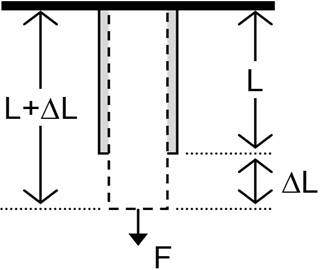
The design of a boom must consider the properties of the materials used to build the boom. The mechanical properties and deformation of solids are explained by stress and strain. When an external force is applied to a material, it changes shape (e.g. changes length and cross-section perpendicular to the length). Understanding how deformation will affect materials is a critical consideration in boom design. According to Serway and Beichner in “Physics for Scientists and Engineers,” stress is the external force acting on an object per unit cross sectional area. Strain is the measure of deformation resulting from an applied stress (Figure 6).
The expression (1) for tensile stress shows the relationship between an applied force and the cross-sectional area.
(1)
In (1), σ is the stress, F is the applied force, and A is the cross-sectional area of the object perpendicular to the force. The resulting strain (2) is calculated by dividing the change in length of the object by the original length.
(2)
In (2), ΔL is the change in length and L0 is the object's original length.
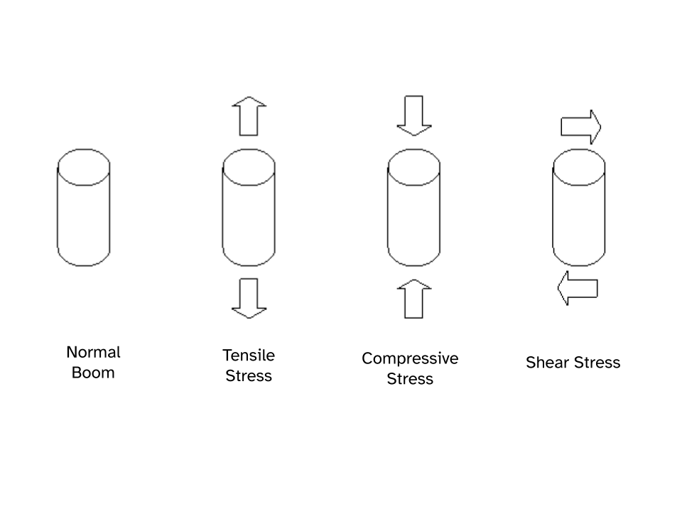
There are three basic types of stresses; tensile (pulling or stretching), compressive (squeezing or squashing), and shear (bending or cleaving). If a rod of material is put under tensile stress, its length increases slightly in the direction of the applied force and its cross-section perpendicular to the direction of the applied decreases. If the rod is placed under compressive stress, its length in the direction of the force will decrease and its cross-section perpendicular to the force will increase. If the rod is placed under shear stress, it will bend in the direction of the applied force and its length and cross-section will be distorted (Figure 7).
Strain is proportional to stress for small values of strain. The proportionality constant depends on the material being deformed and on the type of deformation. The proportionality constant is called the elastic modulus, or Young’s modulus. The moduli for different materials vary considerably and the various moduli for a particular material may also vary significantly. For example, concrete is very strong in compression, but less so in tension, and wood breaks quite easily when bent because its natural grain is anisotropic (properties depend on the direction of the material).
Stress-Strain Curve
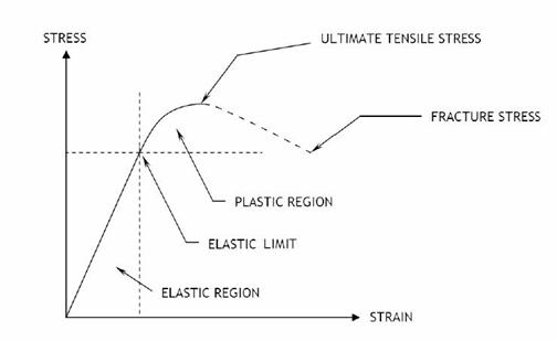
A stress-strain curve graphically shows the relationship between the stress and strain of a material under load (Figure 8). In the elastic region, the material will regain its original shape once the stress or load is removed. In the plastic region, the material loses its elasticity and is permanently deformed.
The elastic limit for a material is the maximum strain it can sustain before it becomes permanently deformed (i.e. if the stress is decreased, the object no longer returns to its original size and shape). If the stress is greater than the elastic limit, the material will plastically deform and for sufficiently large stress ultimately fail. The ultimate tensile strength is the maximum stress a material can undergo. The fracture stress is the point at which the material breaks under tension. Fracture stress is lower than the ultimate tensile strength because as strain increases, the material becomes thinner and thinner. As this necking down process continues, the load that can be supported decreases and the material breaks.
In addition to these intrinsic material factors, the behavior of materials as they age and are used in service must be considered in boom design. These factors do not relate directly to the boom design in this lab, but they must be considered when deciding what material to use for an actual design. The loss of desirable properties through use, called fatigue, is important. Non-static loads, repeated loading and unloading, or loads that include vibrations or oscillations may lead to failure in service. Special care must be taken with live loads and situations where small motions may be magnified by design features.
There are many factors to consider in any design project. When designing and constructing the boom for this competition, consider the materials being used and what might cause those materials to fail under a load.
There are many factors to consider in any design project. When designing and constructing the boom for this competition, remember to consider the materials being used and what might cause those materials to fail under a load.
An important tool in an engineer’s skillset is the use of simulation tools. Many times, complex designs require quick analysis that cannot be done by calculation or prototyping so simulation comes in handy. Simulation saves both time and money. Specifically, finite element analysis (FEA) splits a design up into small components (called a mesh) and solves them all simultaneously to get a complete look at the design’s performance under stress.
Fusion 360’s simulation runs a steady state isotropic simulation on the boom to study mechanical motion and the static state of the boom under a load.
Competition Rules
The competition rules must be followed at all times during the competition. Violation of any of these rules will result in the disqualification of the design.
- The boom is to be secured (i.e. anchored) to the white plastic anchorage
- The boom must extend at least 1.5 m horizontally from the front edge of the anchorage
- The boom may not touch anything but the anchorage
- The basic weight ratio (3) for the competition uses the reaction force in Newtons divided by the boom mass in kilograms
(3)
The winning design will be determined by the design ratio (4), which uses the weight ratio and boom length in meters divided by 1.5 m.
(4)
Design Considerations
- Which aspects of the competition ratio are most advantageous?
- How can the boom be built and/or reinforced to prevent as much deflection as possible?
Materials and Equipment Allowed
The following are the materials that can be used in Fusion 360:
- Two thick dowels (1.1 cm × 122 cm)
- Two thin dowels (0.8 cm × 122 cm)
- Six bamboo skewers (30.5 cm)
- Unlimited dowel connectors
- Boom anchor
Procedure
Build a boom using Fusion 360, simulate it deflecting 20 cm, and record the reaction force.
1. Boom Design
- Before starting on Fusion 360, sketch the design of the boom and plan how it will look and react to the deflection. Determine which materials would be best to use. Do not simply copy the sample boom, be creative.
Note: Fusion 360, like all software, can take time to learn for new users. Reach out to a TA for any help and clarification needed. Some useful tools and functions are given in the Making the Boom section, but learn Fusion 360’s panels and functions beforehand.
2. Importing Parts
- The parts for the boom can be found using this link: add the link. The latest version of Fusion 360 must be downloaded for the parts to show up.
- The files are in a .zip folder so unzip them into a space on the computer before uploading them.
- After storing them on the computer, click the upload button in the Data Panel (Figure 9) to upload the files onto Fusion’s cloud memory. Since Fusion can only read files uploaded to its cloud, upload the files into Fusion before using them.
Figure 9: Data Panel with Boom Connectors Uploaded
3. Making the Boom
- The files can be imported into a new Fusion 360 file by simply dragging and dropping them into the space. You can also right click the components and select the “insert into current design” (Figure 10). Save the blank file before assembling the boom.
- The first part that should be imported is the anchor. Since the anchor is the only piece that will be connected, it is important to design around it.
- Import the other parts based on the design. Connect all the parts to complete the model.
Figure 10: Inserting the Anchor after uploading
Take time to get comfortable with moving each part around and keep in mind that Fusion 360 is a 3-dimensional workspace. This means that depth is not shown on a 2D screen so use the cube in the top right to change the view and make sure the components fit together. Also keep in mind in a CAD software there are no connections or a ground between the objects. Both the ground and the connections will be manually made when the simulation is set up. (Attempting to make the model’s connections as close as possible will make it less likely for there to be errors in the simulation).
- A short video is provided for reference.
ATTACH VIDEO IN DRIVE HERE
- With the tools listed and the parts given, design the boom on Fusion 360.
