Lab 4 Lighting System Backup
From EG1004 Lab Manual
Revision as of 17:58, 22 August 2016 by Jbringardner (talk | contribs) (Created page with "== Design 2: Lighting System == Build a VI that simulates a lighting system in a house with four rooms. The design must include four lights (LEDs) and at least five switches &mda…")
Design 2: Lighting System
Build a VI that simulates a lighting system in a house with four rooms. The design must include four lights (LEDs) and at least five switches — one switch per light and one master switch that will turn all of the lights off simultaneously (think of this as a circuit breaker). The program should also interact with real LEDs located on the NI-ELVIS board.
- The front panel of the program should include five switches and four LEDs.
- The back panel requires a case structure for the master switch to turn off all the lights.
- In order to control the LEDs on the NI-ELVIS board, a NI ELVISmx Digital Writer node is required on the back panel.
- To access the NI ELVISmx Digital Writer node, click on Measurement I/O on the functions palette, open NI ELVISmx, and select Digital Writer. (see Figure 19)
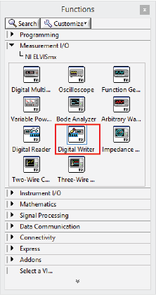 Figure 19: NI ELVISmx measurement I/O functions.
- Once these are placed on the back panel, the NI ELVISmx Digital Writer dialog box will open. Click OK.
- The NI ELVISmx Digital Writer is used for writing information to the NI-ELVIS board. For the purposes of this lab, only two pieces of information need to be presented to the Digital Writer node: DO Lines and Lines to Write.
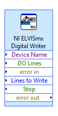 Figure 20: NI ELVISmx Digital Writer.
- DO Lines (Boolean array): This determines which DIO rows on the NI-ELVIS board will be activated (in other words, which LEDs will light up).
- Lines to Write (ring constant): This determines which eight DIO rows can work on the NI-ELVIS board.
- For the purposes of this lab, DIO lines 0–7 will be utilized. To establish this setting, right-click the Lines to Write row on the NI ELVISmx Digital Writer, select Create, followed by Constant. The Operate Value tool can be used to manipulate this value. By default, it is set to 0–7.
- The switches should be wired to a Build Array icon, along with four False constants. Conceptually, think of a vehicle that only departs when all the seats are filled. In this case, the DO Lines is a road only allows vehicles with eight passengers to travel to the NI-ELVIS board. So in order for information to flow from the VI to the NI-ELVIS board, Build Array must provide a vehicle (i.e., an array) with eight passengers or outputs (i.e., the four Boolean switches and four False constants). Build Array can be found under Programming on the functions palette by clicking Array. (see Figure 21)
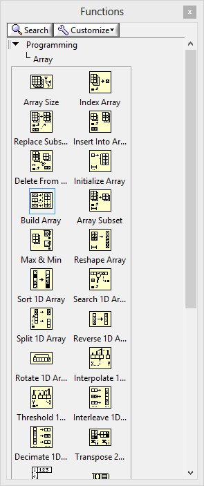 Figure 21: Array programming functions.
- Also keep in mind that if the master switch is off, then all of the LEDs connected to the NI-ELVIS board should shut off as well.
- To access the NI ELVISmx Digital Writer node, click on Measurement I/O on the functions palette, open NI ELVISmx, and select Digital Writer. (see Figure 19)
- In order for the LEDs on the NI-ELVIS board to light up, wires must connect the DIO lines (rows 0–23) directly to the LEDs on the NI-ELVIS board (rows 35–42).


