Difference between revisions of "Introduction to Revit"
| Line 16: | Line 16: | ||
:: <h2 style="margin-left: -4.1em;"> Setting up the file </h2> | :: <h2 style="margin-left: -4.1em;"> Setting up the file </h2> | ||
# Start AutoCAD and open a new file | # Start AutoCAD and open a new file | ||
#: [[Image:lab_3dprint_1.png|frame|center|Figure 1:.]] | |||
# Select the AutoCAD 3D template | # Select the AutoCAD 3D template | ||
#: [[Image:lab_3dprint_2.png|frame|center|Figure 2:.]] | |||
# Modify the units for the drawing | # Modify the units for the drawing | ||
#: [[Image:lab_3dprint_3.png|frame|center|Figure 3:.]] | |||
# Change the length unit type to Engineering | # Change the length unit type to Engineering | ||
#: [[Image:lab_3dprint_4.png|frame|center|Figure 4:.]] | |||
#: <h2 style="margin-left: -4.1em;"> File formats and viewing mode </h2> | #: <h2 style="margin-left: -4.1em;"> File formats and viewing mode </h2> | ||
# AutoCAD drawing files formats include | #: AutoCAD drawing files formats include | ||
## DWG – the primary drawing file for the 3D model view | #:# DWG – the primary drawing file for the 3D model view | ||
## STL – the file exported from AutoCAD for input into 3D printing software | #:# STL – the file exported from AutoCAD for input into 3D printing software | ||
## DWT – the file of the sheet set seen in the layout view | #:# DWT – the file of the sheet set seen in the layout view | ||
## DXF – a drawing format for compatibility with other software | #:# DXF – a drawing format for compatibility with other software | ||
## PLT – the file sent to the printer of the layout view | #:# PLT – the file sent to the printer of the layout view | ||
# The default AutoCAD view is model view, click on the layout view | # The default AutoCAD view is model view, click on the layout view | ||
#: [[Image:lab_3dprint_5.png|frame|center|Figure 5:.]] | |||
# Change to model space in the layout view to change the viewport | # Change to model space in the layout view to change the viewport | ||
#: [[Image:lab_3dprint_6.png|frame|center|Figure 6:.]] | |||
#: <h2 style="margin-left: -4.1em;"> Designing the EG Keychain </h2> | #: <h2 style="margin-left: -4.1em;"> Designing the EG Keychain </h2> | ||
# Open the file “Lab 1 AutoCAD Template” | # Open the file “Lab 1 AutoCAD Template” | ||
#: [[Image:lab_3dprint_7.png|frame|center|Figure 7:.]] | |||
# Open the layer properties and click the lightbulb next to the EG Logo layer | # Open the layer properties and click the lightbulb next to the EG Logo layer | ||
## Layers are a useful way to separate different components of a drawing file | ## Layers are a useful way to separate different components of a drawing file | ||
| Line 35: | Line 42: | ||
## Separating model features (e.g. plumbing and electrical) allows separate viewing | ## Separating model features (e.g. plumbing and electrical) allows separate viewing | ||
## Turn the EG Logo layer back off by clicking the lightbulb | ## Turn the EG Logo layer back off by clicking the lightbulb | ||
#: [[Image:lab_3dprint_8.png|frame|center|Figure 8:.]] | |||
# Fill the EG Logo text outline by typing the command REGION | # Fill the EG Logo text outline by typing the command REGION | ||
#: [[Image:lab_3dprint_9.png|frame|center|Figure 9:.]] | |||
# In general AutoCAD commands operate with the same basic steps | # In general AutoCAD commands operate with the same basic steps | ||
## Type the command | ## Type the command | ||
| Line 42: | Line 51: | ||
### Enter quantity (type and hit enter) | ### Enter quantity (type and hit enter) | ||
### Specify position (click on screen) | ### Specify position (click on screen) | ||
## Hit the enter | ## Hit the enter key to execute command | ||
# Use the command DRAWORDER to move the outlines of the “Rs” and “A” to the back | # Use the command DRAWORDER to move the outlines of the “Rs” and “A” to the back | ||
# Use the command SUBTRACT to remove the holes in the “Rs” and “A” | # Use the command SUBTRACT to remove the holes in the “Rs” and “A” | ||
#: [[Image:lab_3dprint_10.png|frame|center|Figure 10:.]] | |||
# Use the EXTRUDE command to add 3/8” height to the text | # Use the EXTRUDE command to add 3/8” height to the text | ||
#: [[Image:lab_3dprint_11.png|frame|center|Figure 11:.]] | |||
# Use the REGION command on the box outline and EXTRUDE to 1/4” | # Use the REGION command on the box outline and EXTRUDE to 1/4” | ||
# Create a keychain hole | # Create a keychain hole | ||
| Line 53: | Line 64: | ||
## Change the DRAWORDER of the box to the back | ## Change the DRAWORDER of the box to the back | ||
## SUBTRACT the cylinder from the box | ## SUBTRACT the cylinder from the box | ||
#: [[Image:lab_3dprint_12.png|frame|center|Figure 12:.]] | |||
# Select all features and save as an STL file | # Select all features and save as an STL file | ||
#: [[Image:lab_3dprint_13.png|frame|center|Figure 13:.]] | |||
# Open the STL file in MakerBot Desktop, click rescale object to convert from inches to millimeters | # Open the STL file in MakerBot Desktop, click rescale object to convert from inches to millimeters | ||
#: [[Image:lab_3dprint_14.png|frame|center|Figure 14:.]] | |||
# Explore the features of 3D printing software (scaling, position, rotation) | # Explore the features of 3D printing software (scaling, position, rotation) | ||
#: [[Image:lab_3dprint_15.png|frame|center|Figure 15:.]] | |||
# Additional AutoCAD instruction can be found in the [[AutoCAD Skill Builder]] | # Additional AutoCAD instruction can be found in the [[AutoCAD Skill Builder]] | ||
{{Laboratory Experiments}} | {{Laboratory Experiments}} | ||
Revision as of 21:13, 31 August 2015
Objective
In this exercise, you will be introduced to additional software used by technical professionals. You will learn basic technical design methods using Computer-Aided Design (CAD) software, specifically AutoCAD. Later on in the course, you will use this knowledge to create designs, particularly in your semester-long design project.
Create an EG Logo Keychain in AutoCAD 2016 to export for a 3D print.
Overview
Computer-Aided Design
Computer-Aided Design (CAD) programs allow engineers to make precise scaled drawings in less time than more traditional methods. CAD drawing allows designers to make changes easily and efficiently making them more productive. You will need to understand the fundamentals of Computer-Aided Design to progress in your career.
This exercise has been designed to introduce the basics of CAD drawing.
3D Printing
Blurb.
Procedure
Setting up the file
- Start AutoCAD and open a new file
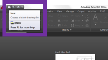 Figure 1:.
- Select the AutoCAD 3D template
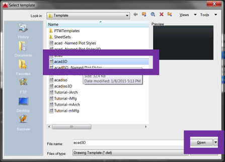 Figure 2:.
- Modify the units for the drawing
 Figure 3:.
- Change the length unit type to Engineering
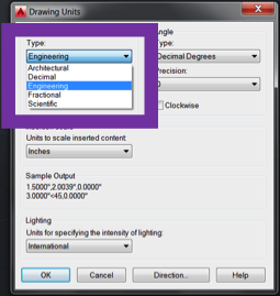 Figure 4:.
File formats and viewing mode
- AutoCAD drawing files formats include
- DWG – the primary drawing file for the 3D model view
- STL – the file exported from AutoCAD for input into 3D printing software
- DWT – the file of the sheet set seen in the layout view
- DXF – a drawing format for compatibility with other software
- PLT – the file sent to the printer of the layout view
- The default AutoCAD view is model view, click on the layout view
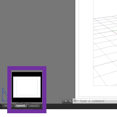 Figure 5:.
- Change to model space in the layout view to change the viewport
 Figure 6:.
Designing the EG Keychain
- Open the file “Lab 1 AutoCAD Template”
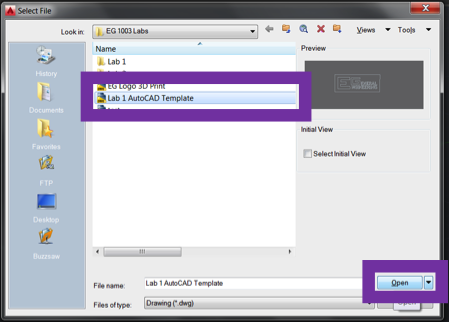 Figure 7:.
- Open the layer properties and click the lightbulb next to the EG Logo layer
- Layers are a useful way to separate different components of a drawing file
- In this DWG, the EG Logo layer is the image file used to create the text outline
- Separating model features (e.g. plumbing and electrical) allows separate viewing
- Turn the EG Logo layer back off by clicking the lightbulb
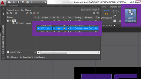 Figure 8:.
- Fill the EG Logo text outline by typing the command REGION
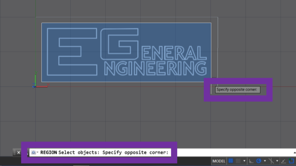 Figure 9:.
- In general AutoCAD commands operate with the same basic steps
- Type the command
- Choose command parameters and objects
- Select object (hit enter after)
- Enter quantity (type and hit enter)
- Specify position (click on screen)
- Hit the enter key to execute command
- Use the command DRAWORDER to move the outlines of the “Rs” and “A” to the back
- Use the command SUBTRACT to remove the holes in the “Rs” and “A”
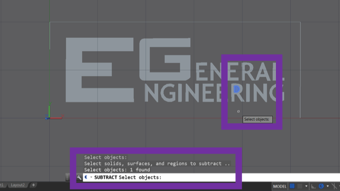 Figure 10:.
- Use the EXTRUDE command to add 3/8” height to the text
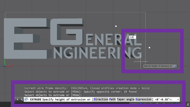 Figure 11:.
- Use the REGION command on the box outline and EXTRUDE to 1/4”
- Create a keychain hole
- Draw a CIRCLE with radius 1/8”
- Change the DRAWORDER of the box to the back
- EXTRUDE the circle -1/4”
- Change the DRAWORDER of the box to the back
- SUBTRACT the cylinder from the box
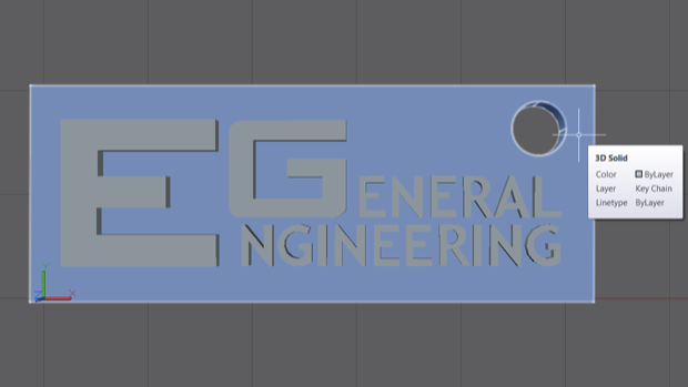 Figure 12:.
- Select all features and save as an STL file
 Figure 13:.
- Open the STL file in MakerBot Desktop, click rescale object to convert from inches to millimeters
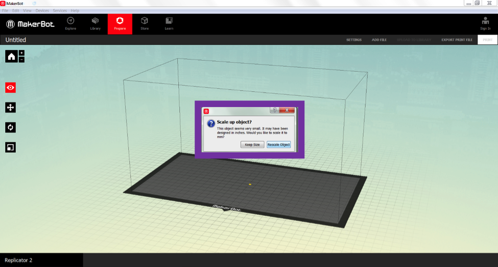 Figure 14:.
- Explore the features of 3D printing software (scaling, position, rotation)
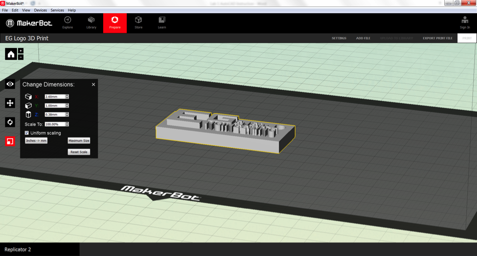 Figure 15:.
- Additional AutoCAD instruction can be found in the AutoCAD Skill Builder


| ||||||||