Computer Aided Design Competition
Pre-Lab
Please visit the MakerSpace before this lab and complete their Safety Orientation. Sign up for sessions provided specifically for EG1003 students here If you have already completed the Safety Orientation, please fill out this form to receive credit. There will be a 20 point penalty on the lab report for not completing this training before the beginning of this lab.
Please view the videos that explain this lab prior to performing the exercise to ensure it will be completed in the time allotted. The required videos are listed under this page on the main page of the manual.
Objective
The experimental objective of this lab is to analyze and modify a poorly-designed part using Fusion 360 and enter it in a competition against other designs. The competition will be judged by a ratio that uses safety factor and volume. The highest ratio wins. A second objective is to design an apartment using Revit.
Overview
Fusion 360
Autodesk Fusion 360 is a cloud-based software that uses remote servers hosted via the internet to process, store, and compute data. This computer aided design (CAD) tool creates precisely scaled drawings. These drawings are turned into 3D models that are used to visualize designs through photorealistic renderings and to simulate how a design performs under real world conditions. Fusion 360 can also be used for designing in computer aided manufacturing (CAM), computer aided engineering (CAE), animation, and more.
The two workspaces in Fusion 360 that will be used in this experiment are Design and Simulation (Figure 1). The Design workspace is used for creating mechanical designs that contain information about geometric constraints, and the Simulation workspace is used for applying loads to the design to observe the possibility of deformation or failure.

Design has two tabs: Create and Modify. The Create and Modify tabs contain the functions needed for sketching and building a 3D model. They allow for creating and modifying sketches when in sketch mode (Figure 2).

A Sketch creates the 2D shapes that are the bases for all 3D models. When first sketching the shapes, they do not have to have accurate dimensions or scale. Using the Sketch Dimension tool and the Constraints functions, the base shape and 3D model can be edited without starting over (Figure 3).

Once a sketch is complete, the Create and Modify tabs are also used to generate the 3D model (Figure 4).

The Extrude and Sweep tools are used to give direction and depth to the 3D model. Extrude projects the initial sketch outward to create a model. The Sweep tool creates a 3D model of a predetermined surface (profile) along a specific path (Figure 5). Although this tool is more efficient than creating multiple shapes and cutting, it can be a bit challenging and so creating the desired shapes and then using an Extrude cut should be sufficient.

The Simulation workspace can run simulations to test how a part will perform under real world conditions. A Static Stress simulation, for example, analyzes the deformation, stress, and safety factor in a model from structural loads and constraints. These assumptions are based on a linear response to stress when the load being applied is known and constant. The results determine if a design will deform excessively or fail (break) from the loads applied. To run the tests, conditions are placed on the model.
Constraints consist of fixed, pinned, and frictionless support options that prevent motion in specific directions. Fixed constraints prevent all motion and displacement of a part (Figure 6). This would mimic a screw holding a part in place. A pinned support prevents movement in radial, axial, and/or tangential directions, but allows a part to rotate. Frictionless constraints prevent movement normal to the surface. This mimics a wall or floor to prevent motion perpendicular to the surface.

A Load is the force being applied to the model (Figure 7). The force is characterized by the direction, the point of application, and the magnitude of the force being applied.

A Mesh is a boundary along the model made up of polygons that determine the precision of the analysis test (Figure 8). At every vertex, the analysis is run and results are provided. The more polygons that are generated in the mesh, the more precise the results will be, but the longer it will take to run the simulation and produce the results. Always generate a new mesh when a part is altered.

The safety factor is the ratio of how much stronger a system is than the expected load. It is the measure of the load an object can sustain before permanent deformation or fracture. A common, acceptable safety factor is at least three, and any value below that is unacceptable and will likely lead to structural failure.
The physical properties of certain materials dictate how they behave under applied loads. As introduced in the Boom Construction Competition lab, the Young’s modulus, or modulus of elasticity, of a material is the measure of stiffness of an object. It is described as the tendency of an object to deform axially when a force is applied in the axial direction. The yield strength of a material is the point at which the material begins to plastically deform and the shape of the object is permanently altered. The ultimate tensile strength (UTS) of a material is the maximum stress that the material can withstand before structurally failing, which usually involves bending permanently or breaking.
Revit
Autodesk Revit is a building modeling software for architects, landscape architects, civil engineers, structural engineers, and contractors. Revit allows users to design buildings and other structures in 3D while allowing 2D drafting elements. Revit can be used to easily create various home layouts from the floor plan to electrical and plumbing schematics, and design many other elements.
The floor plan is the fundamental layout of any building. It displays the skeleton of the structure. It shows all walls, windows, and entrances and can also be furnished when being used for demonstration purposes. Different types and thicknesses of walls are used for different purposes. When designing a house, most of the interior walls are not as thick as exterior walls or walls separating public from private locations.
The electrical plan is a mechanical template of the floor plan and shows the light fixtures, system components, and appliances, such as refrigerators, light switches, and wires connecting lights to switches.
Specifications
Fusion 360
- This portion of the lab is a competition to redesign the same part to obtain the highest competition ratio (1)
- The redesigned part must have a safety factor of at least 3
- The redesigned part must not have more than double the volume of the original part
- The applied forces and fixed constraints cannot be altered
- The thickness of the base and the proportions of the original part cannot be altered. The supports can be altered if and only if they do not take away or add from the base of the model
- The winning design will receive extra credit towards the lab report grade for this lab
- Only the materials in Table 1 may be used when modifying the part
Table 1: Allowed Materials and their Properties Material Aluminum Steel Copper Lead Titanium Modulus of Elasticity (GPa) 69 200 118 14 120 Yield Strength (MPa) 275 207 33 9 276 Ultimate Tensile Strength (MPa) 310 345 210 18 345
- The competition will be decided by a ratio (1) that uses the part’s safety factor and volume (make sure to give the Lab TA the volume in mm3)

(1)
Revit
It is the year 2020 and your design firm has been contracted by New York City Mayor Bill de Blasio to solve a problem for many families. There are 1.8 million one and two-person households in the city, but there are only about one million studio and one-bedroom apartments. The task is to a create a 350-400 square foot apartment for residents/college students. This apartment should be furnished. It should have a bathroom with the appropriate furnishings, a kitchen with the appropriate furnishings, and a bedroom with a bed, a table, and a desk. It must have adequate lighting (at least one window) and space. Design an apartment layout with the following specifications.
- A 350-400 square foot floor plan layout of the entire apartment
- An electrical plan for the entire apartment
- Upon completion of the apartment design, groups have the choice to create a realistic rendering and 3D walkthrough of the apartment to receive extra credit
- To receive the extra credit, both the rendering and the walkthrough must be included in the Team PowerPoint Presentation
Design Considerations
Fusion 360
- Do not simply add a long or large block to the redesigned part
- Consider bridges, cranes, and other systems that use structural support in the redesign
- Consider which material will increase the safety factor (Table 1)
- Using the contents from the Boom Construction Competition lab, how can the part be modified to support higher loads?
Revit
- How well was space maximized in this very small apartment?
- Was the necessary storage added?
- Is the layout coherent and creative?
- Could a person comfortably live here?
Materials and Equipment
- A lab PC
- Fusion 360
- Revit
Procedure
1. Fusion 360
Parts
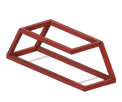
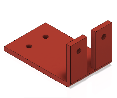
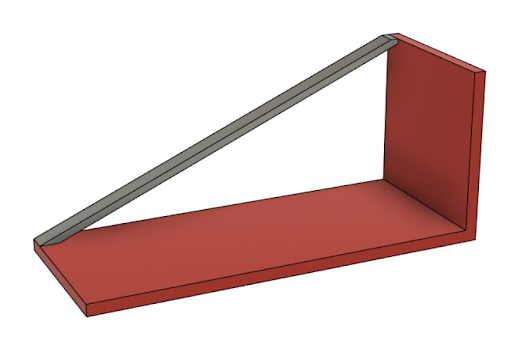
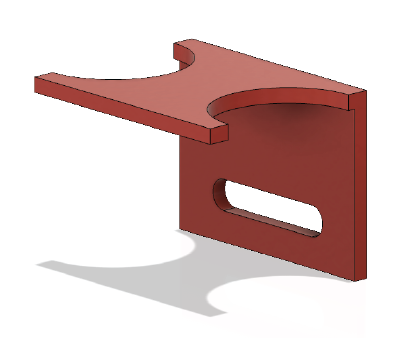
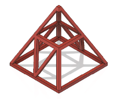
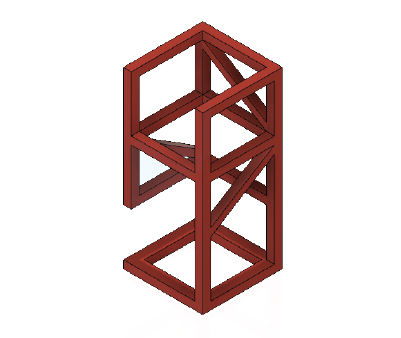
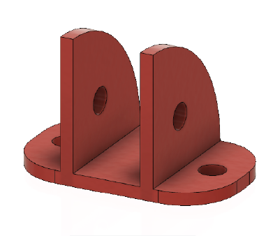
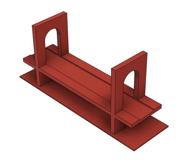
Click on the image of the part to download the Fusion 360 file for that part. Figures 9 through 16 show in red what cannot be modified in each part. The red areas cannot be cut, made longer, or thicker. Components can be added, such as fillets, chamfers, or other extrusions, including lofts and sweeps.
Procedure
- Download the part to be modified as determined by the Lab TA. Extract the ZIP folder that was downloaded to obtain the F3D file.
- Open Fusion 360. Go to File > Open and select the downloaded part. Select the Design workspace in the top left of the window.
- Open the Bodies in the Browser on the left side of the window, right click on the body of interest, and click Properties (Figure 18).
- From the Properties dialog, record the volume of the body in mm3.
- Click the workspace drop-down menu at the top left of the window and change the workspace to Simulation.
- Open the Static Stress study in the Browser, and open the Study Materials tab (Figure 19). Record the material being used.
- Determine the location the load is being applied (Figure 20). Double click the blue force arrow and record the magnitude of the force in Newtons.
- In the Browser, right click Mesh then select Generate Mesh (Figure 21). If the mesh is already generated and a error occurs, select OK.
- In the Browser, right click Results and select Solve. Follow the Solve dialog until the simulation status is complete. Click Close and the results should look like Figure 22.
- Record the minimum safety factor that occurs in the design.
- Sketch a possible solution to add structural stability to the broken part that would add extra support against the force being applied, remembering what cannot be modified. Recall that the modified design should aim to generate a minimum safety factor of 3. Have the sketch approved by a TA.
- Go back to the Design workspace in Fusion 360 and use the tools shown to add support to the original part (i.e. Extrude and Sweep).
- Change the material of the part if needed by right clicking on the current Study Material in the Browser, as it can increase the safety factor.
- Once the part has been modified, go back to the Simulation workspace.
- Run the analysis again with the modified part. Right click Mesh and select Generate Mesh in the Browser.
- Solve the Results and observe the minimum safety factor of the modified design. The model may become bent as the results are exaggerated in the simulation to gain a better understanding of how the part moves with an applied load.
- If the new part does not have a factor of safety of at least 3, add additional supports and/or change the material of the part and run the simulation again.
- Once the required safety factor has been achieved, record the minimum safety factor and volume of the modified part. Give the values of the minimum safety factor and volume of the unmodified and modified parts to the TA to calculate the competition ratio and see the design’s standing in the competition.


2. Revit
Procedure
- Sketch a solution to the prompt and indicate the square footage. Have the sketch approved by a TA.
- Open Revit. Select New > Architectural Template (Figure 23).
- There are four major sections used to create and modify the building in Revit. The Quick Access Toolbar is in red, the project ribbon in yellow, the Properties panel in green, and the Project Browser panel in blue (Figure 24). If any of the sections are accidentally removed from view, they can be reinserted by going to View > User Interface (rightmost icon) in the ribbon. File:Lab 4 Figure 24.PNGFigure 24: Revit Interface
- In the ribbon, go to the Manage tab and select Project Units (or type UN) under the Settings section (Figure 25). Click the Length value and select "Feet and fractional inches” with rounding to the nearest 1/32”. Click OK.
- Ensure the Properties panel is open by right clicking anywhere and clicking on Properties.
- Ensure the Level 1 floor plan is selected in the Project Browser on the left side of the window by double clicking on Level 1 under Floor Plans.
- Create the exterior walls by going to the Architecture tab in the ribbon and selecting Wall (Figure 26).
- Make sure the walls are 8” thick and 10’ high. The thickness and height of the walls can be changed in the Properties panel (Figure 27). File:Lab 4 Figure 27.PNGFigure 27: Wall Properties
- The Base Constraint changes where the bottom of the wall is placed in reference to the different levels.
- The Base Offset adjusts the height difference between the level and the base of the wall.
- The Top Constraint determines where the top of the wall is located. If the top constraint is selected to be Unconnected, then the Unconnected Height can be used to determine a numerical value for the height of the wall.
- Insert the interior walls (6” thick and 10’ high) for the bathroom and any other walls if desired. The type of wall (thickness) can be changed in the drop-down menu in the Properties panel (Figure 28). File:Lab 4 Figure 28.PNGFigure 28: Changing Wall Types
- Insert the floor by using the Floor tool in the Architecture tab of the ribbon and selecting the boundary where the floor will be placed. The boundary can be made by selecting the walls or by creating individual lines from the Draw section of the Modify | Create Floor Boundary tab in the ribbon (Figure 29). To complete the floor, click on the green check mark in the ribbon. File:Lab 4 Figure 29.PNGFigure 29: Create Floor Boundary
- Insert doors and windows in the apartment.
- Go to Insert > Load Family > Doors/Windows for a wide range of doors and windows (Figure 30). Doors should be 3’ wide and 7’ tall (No specifications for windows).
- File:Lab 4 Figure 30.PNGFigure 30: Load Family Tool
- Go back to the Architecture tab of the ribbon and select Door/Window (Figure 31) and select the loaded door/window from the Properties panel. They can then be placed by clicking in the floor plan.
- File:Lab 4 Figure 31.PNGFigure 31: Door and Window Tools
- Once placed, the direction of the doors and windows can be changed with the arrow couples (Figure 32).
- Go to Insert > Load Family > Doors/Windows for a wide range of doors and windows (Figure 30). Doors should be 3’ wide and 7’ tall (No specifications for windows).
- When loading furniture or appliances, go to the Architecture tab of the ribbon and select Component > Place a Component (or type CM).
- Furniture and appliances can be added with the Load Family tool like doors and windows. Only the furniture and appliances from the specifications must be in the floor plan including the entire bathroom. Table 2 shows the folder paths for all the files needed in this lab.


Table 2: File Paths for Required Components Component File Path Sink US Imperial > Plumbing > MEP > Fixtures > Sinks Toilet US Imperial > Plumbing > MEP > Fixtures > Water Closets Shower US Imperial > Plumbing > MEP > Fixtures > Shower Bed US Imperial > Furniture > Beds Kitchenette US Imperial > Special Equipment > Domestic Table US Imperial > Furniture > Tables Desk US Imperial > Furniture > Tables Door US Imperial > Door > Residential
- Add furniture to the floor plan. The components can be rotated before being placed by pressing the space bar.
- Once the families are loaded, they can be placed by going to Component > Place a Component in the Architecture tab of the ribbon and by switching in the Properties tab (Figure 33). File:Lab 4 Figure 33.PNGFigure 33: Changing Component Families
- To insert a ceiling or ceiling appliances, the ceiling plan in the Project Browser must be selected. Go to Level 1 in the Ceiling Plans (Figure 34). File:Lab 4 Figure 34.PNGFigure 34: Ceiling Plans
- Use the Ceiling tool in the Architecture tab of the ribbon to create the ceiling (Figure 35). File:Lab 4 Figure 35.PNGFigure 35: Ceiling Tool
- The ceiling is created with the same method as the floor, by selecting a boundary where the ceiling will be placed. The individual walls can be selected to create the boundary by creating a Sketch Ceiling, or entire areas can be selected for the boundary using the Automatic Ceiling (Figure 36). Don’t forget to complete the ceiling by clicking the green check mark in the ribbon. File:Lab 4 Figure 36.PNGFigure 36: Sketch Ceiling and Automatic Ceiling Tools
- Navigate back to the Level 1 floor plan in the Project Browser. Insert the electrical appliances in the apartment with the Component tool in the Architecture tab of the ribbon and using the file paths provided in Table 3.
Table 3: File Paths for Required Electrical Components Component File Path Light Switch US Imperial > Electrical > MEP > Electric Power > Terminals Ceiling Light US Imperial > Lighting > MEP > Internal
- For ceiling lights, go back to the Level 1 ceiling plan in the Project Browser. Select the lights that are to be placed with the Component tool in the Architecture tab of the ribbon. Once the lighting fixture is selected, select Place on Face in the Placement section of the Modify | Place Component tab of the ribbon to freely place the lights on the ceiling (Figure 37). File:Lab 4 Figure 37.PNGFigure 37: Place on Face Tool
- Go back to the Level 1 floor plan in the Project Browser. Notice that the light fixtures on the ceiling cannot be seen in the floor plan. They must be made visible to create the electrical wiring.
- In the Properties panel, go to the Underlay subtab and change the Range: Base Level to Level 1 and Underlay Orientation to Look up (Figure 38). This will allow the ability to “look up” at the ceiling and see the lighting fixtures on the ceiling in the floor plan.
- Connect the lights and switches with electrical wiring. Navigate to the Systems tab in the toolbar and select the Wire tool (Figure 39).
- Connect the lights to the switches. Make sure the lights and switches are properly connected to the wire by hovering over the fixture and seeing a pink circle with an X (Figure 40).
- In the Quick Access Toolbar, select Default 3D View (small house icon) to view the project in 3D (Figure 41). File:Lab 4 Figure 41.PNGFigure 41: Default 3D View Tool
- Save the file as an Autodesk Revit File (RVT) file. Take screenshots of the project and submit the RVT file on the EG1003 website by 11:59 PM the night before the next lab.


Assignment
Individual Lab Report
Follow the lab report guidelines laid out in the page called Lab Report Format in the Technical Writing section of the manual. The following points should be addressed in the appropriate section of the lab report.
- Include at least two simulations (before and after modifying the part)
- Define CAD, Fusion 360 & Revit, safety factor, and ultimate tensile strength
- Why is CAD software, such as Revit, Fusion 360, AutoCAD, or SolidWorks, an important tool for engineers?
- Should there be a universal CAD software? What are the pros and cons of this?
- Discuss minimal design. How did having a constrained volume impact the design process?
- How did the redesign compare with other redesigns? Did the material have an impact on the safety factor and if so, why?
- Discuss the advantages and disadvantages of the design
- Why are smaller apartments, such as the ones created in this lab, becoming more desirable?
- How can the electricity used in an apartment be minimized through architectural design?
Remember: Lab notes must be taken. Experimental details are easily forgotten unless written down. EG1004 Lab Notes Paper can be downloaded and printed from the EG1004 Website. Use the lab notes to write the Procedure section of the lab report. At the end of each lab, a TA will scan the lab notes and upload them to the Lab Documents section of the EG1004 Website. One point of extra credit is awarded if the lab notes are attached at the end of the lab report. Keeping careful notes is an essential component of all scientific practice.
Team PowerPoint Presentation
Follow the presentation guidelines laid out in the page called EG1003 Lab Presentation Format in the Technical Presentations section of the manual. When preparing the presentation, consider the following points:
- Why is CAD software, such as Revit, Fusion 360, AutoCAD, or SolidWorks, an important tool for engineers?
- Include the four basic CAD drawing views (top, most detailed side, front, and isometric) of the part
- The mechanical part before modifications
- The mechanical part after modifications
- Why are smaller apartments, such as the ones created in this lab, becoming more desirable?
- How can the electricity used in an apartment be minimized through architectural design?
- How is simulation used in engineering design?
- Explain the material selected for the redesign of the part
- How did having a constrained volume impact the design process?
- Define safety factor
- How did the redesign compare with other redesigns?
- Did the material have an impact on the safety factor, and if so, why?
- Include the 3D rendering and walkthrough video (to receive extra credit)
References
There were no references used.
| ||||||||